background image

5

ASSEMBLY

1.

Insert four M10 x 50mm Carriage Bolts (29) up

through the Right Stabilizer (2). Attach the Right

Upright Base (4) to the Stabilizer with the indicat-

ed Bolts and two M10 Nylon Locknuts (58). Do

not tighten the Locknuts yet.

Repeat this step with the Left Stabilizer (1)

and Left Upright Base (3). Note: Make sure

that the indents around the holes in the

Stabilizer are on the bottom.

1

Before beginning assembly, make sure you

understand the information in the box

above.  For help identifying small parts,

use the PART IDENTIFICATION CHART.

1

2

58

58

4

29

29

Indents

3

To hire an authorized service technician to

assemble the weight bench, call toll-free 

1-800-445-2480.

Before beginning assembly, carefully read the

following information and instructions:

• Because of its weight and size, the weight bench

should be assembled in the location where it will

be used. Make sure that there is enough clear-

ance to walk around the weight bench as you

assemble it.

• Place all parts in a cleared area and remove the

packing materials. Do not dispose of the packing

materials until assembly is completed. 

• Tighten all parts as you assemble them, unless

instructed to do otherwise. 

• As you assemble the weight bench, make sure all

parts are oriented as shown in the drawings.  

• Assembly requires two people.
• For help identifying small parts, use the PART

IDENTIFICATION CHART.

The included grease, and the following tools

(not included) may be required for assembly: 

• Two adjustable wrenches
• One rubber mallet
• One standard screwdriver

• One Phillips screwdriver
• Clear tape or masking tape, and soapy water.
Assembly will be more convenient if you have a

socket set, a set of open-end or closed-end

wrenches, or a set of ratchet wrenches.

Make Things Easier for Yourself
Everything in this manual is designed to ensure

that the weight bench can be assembled suc-

cessfully by almost anyone. However, the weight

bench has many parts and the assembly

process will take time. By setting aside plenty of

time, assembly will go smoothly. 

Summary of Contents for GGBE1285.0

Page 1: ...er in the space above for future reference Serial Number Decal Under Seat QUESTIONS As a manufacturer we are com mitted to providing complete customer satisfaction If you have questions or if a part is damaged or missing PLEASE CONTACT OUR CUSTOMER SERVICE DEPARTMENT DIRECTLY CALL TOLL FREE 1 877 776 4777 Mon Fri 6 a m 6 p m MST ON THE WEB www goldsgympowerflex com USER S MANUAL ...

Page 2: ... Remove the PART IDENTIFICATION CHART and PART LIST EXPLODED DRAWING before begin ning assembly GOLD S GYM is a registered trademark of Gold s Gym International Inc This product is manufactured and distributed under license from Gold s Gym International Inc TABLE OF CONTENTS The decal shown here has been placed on the weight bench If the decal is missing or illegible please call the toll free tele...

Page 3: ...t bench at all times 11 Always wear athletic shoes for foot protec tion while exercising 12 The weight bench is designed to support a maximum user weight of 300 pounds and a maximum total weight of 610 pounds Do not place more than 310 pounds including the barbell on the weight rests Do not place more than 150 pounds on the leg lever Note The weight bench is designed to be used with an Olympic bar...

Page 4: ...nefit read this manual carefully before using the weight bench If you have questions after reading this manual see the front cover of this manu al To help us assist you please note the product model number and serial number before calling The model number is GGBE1285 0 The serial number can be found on a decal attached to the weight bench see the front cover of this manual To avoid a registration ...

Page 5: ... ance to walk around the weight bench as you assemble it Place all parts in a cleared area and remove the packing materials Do not dispose of the packing materials until assembly is completed Tighten all parts as you assemble them unless instructed to do otherwise As you assemble the weight bench make sure all parts are oriented as shown in the drawings Assembly requires two people For help identi...

Page 6: ... Do not tighten the Locknuts yet Attach the Left Rear Support 6 to the Left Upright 31 and Left Upright Base 3 with two M10 x 58mm Bolts 30 the Left Upright Plate 15 and two M10 Nylon Locknuts 58 and an M10 x 93mm Bolt 14 two M10 Washers 43 and an M10 Nylon Locknut 58 Do not tighten the Locknuts yet Repeat this step with the Right Upright not shown and the Right Rear Support not shown 4 Attach the...

Page 7: ...arriage 42 onto the Bench Frame 8 Attach the Front Leg 12 to the Bench Frame 8 with two M8 x 52mm Bolts 59 two M8 x 58mm Bolts 46 six M8 Washers 50 and four M8 Nylon Locknuts 49 Do not tighten the Locknuts yet 7 Set the pins on the Adjustment Tube 9 down into a set of brackets on the Upright Bases 3 4 Tighten the M10 Nylon Locknuts 58 used in steps 1 4 and the M8 Nylon Locknuts 49 used in steps 5 ...

Page 8: ...gh the Seat Frame 10 and into the tube on the Seat Carriage 42 Tighten the four M6 x 40mm Screws 48 used in step 9 9 Attach the Backrest 22 to the two Backrest Frames 17 with four M6 Washers 54 and four M6 x 40mm Screws 48 Do not tighten the Screws yet 8 Attach the tether on the Seat Adjustment Pin 40 to the Seat Fame 10 with an M4 x 16mm Screw 57 Orient the Seat 21 with the wide end on the side s...

Page 9: ... Locknut 58 Do not overtighten the Locknut the Leg Lever must be able to pivot easily 11 23 23 18 18 12 24 12 24 24 12 50 19 18 62 46 61 50 49 58 55 Grease 13 Slide a Pad Tube 24 through a hole in the Front Leg 12 Slide two Foam Pads 23 onto the Pad Tube Repeat this step with the other Pad Tubes 24 and the Leg Lever 18 13 14 Locking Bar 39 31 14 Insert a Weight Rest 39 into the Left Upright 31 and...

Page 10: ...0 to the Curl Post 13 with two M6 x 16mm Screws 41 16 Make sure that all parts are properly tightened before you use the weight bench The use of all remaining parts will be explained in ADJUSTMENTS starting on the next page 20 13 41 ...

Page 11: ...elow Then move the Adjustment Tube 9 to the desired height Make sure the pins in the Adjustment Tube are inserted into a set of brackets on the Upright Bases 3 4 or Uprights 28 31 Finally rest the Backrest on the Adjustment Tube 4 28 31 Pin 3 9 22 ADJUSTMENTS 21 42 45 8 42 21 10 40 Tube ADJUSTING THE SEAT ADJUSTMENT TUBE To move the Seat 21 loosen the T handle 45 and pull it out as far as it will ...

Page 12: ...t not included onto the Weight Tube 19 Secure your weights with a Small Spring Clip 51 To use Olympic weights press a 48mm Round Inner Cap 38 into the Olympic Adapter 47 Attach the Olympic Adapter to the Weight Tube 19 with the M8 x 10mm Set Screw 60 Make sure the Set Screw is on the bottom of the Adapter Secure your weights with the Large Spring Clip not shown WARNING Do not place more than 150 p...

Page 13: ...ise will reshape and strengthen your body plus devel op your heart and lungs PERSONALIZING YOUR EXERCISE PROGRAM Determining the exact length of time for each workout as well as the number of repetitions or sets completed is an individual matter It is important to avoid overdo ing it during the first few months of your exercise pro gram You should progress at your own pace and be sensitive to your...

Page 14: ...ocopied and used to schedule and record your workouts List the date the exercises performed the resistance used and the numbers of sets and repetitions com pleted Record your weight and key body measure ments at the end of every month Remember the key to achieving the greatest results is to make exercise a regular and enjoyable part of your everyday life O P Q R S T U V X W N M J G F H I K E C D B...

Page 15: ...IGHT SETS REPS EXERCISE WEIGHT SETS REPS EXERCISE WEIGHT SETS REPS AEROBIC EXERCISE AEROBIC EXERCISE TUESDAY Date WEDNESDAY Date THURSDAY Date FRIDAY Date Make photocopies of this page for scheduling and recording your workouts ...

Page 16: ...M6 x 16mm Screw 41 25mm Round Outer Cap 62 M8 x 70mm Bolt 33 M10 x 70mm Bolt 55 M10 x 58mm Bolt 30 48mm Round Inner Cap 38 M8 x 10mm Set Screw 60 M8 x 52mm Bolt 59 M4 x 16mm Screw 57 M10 x 93mm Bolt 14 M10 x 50mm Carriage Bolt 29 M8 x 55mm Bolt 64 M6 x 40mm Screw 48 M10 Washer 43 PART IDENTIFICATION CHART ...

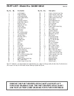
Page 17: ... Left Upright 32 2 25mm x 40mm Inner Cap 33 1 M8 x 70mm Bolt 34 4 45mm Square Inner Cap 35 2 25mm x 50mm Inner Cap 36 4 25mm Square Inner Cap 37 8 38mm x 75mm Inner Cap 38 1 48mm Round Inner Cap 39 2 Weight Rest 40 1 Seat Adjustment Pin 41 6 M6 x 16mm Screw 42 1 Seat Carriage 43 10 M10 Washer 44 4 25mm Round Inner Cap 45 1 T handle 46 3 M8 x 58mm Bolt 47 1 Olympic Adapter 48 4 M6 x 40mm Screw 49 8...

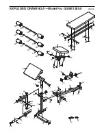
Page 18: ...3 25 24 25 23 58 34 62 50 46 34 61 50 49 34 18 34 19 44 47 60 38 11 37 37 14 58 12 56 59 49 64 64 49 33 45 35 41 41 35 57 40 10 21 51 52 43 36 36 43 58 53 36 48 54 54 48 26 42 26 8 22 17 17 50 50 50 50 50 EXPLODED DRAWING A Model No GGBE1285 0 R0605A ...

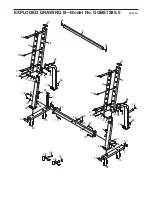
Page 19: ... 14 14 57 57 57 57 57 57 37 37 3 16 4 7 16 6 44 58 43 43 9 14 14 37 37 37 37 58 43 43 58 58 58 58 58 29 29 29 29 58 58 30 58 58 58 58 30 58 58 15 14 14 27 28 31 5 2 1 43 43 43 43 63 EXPLODED DRAWING B Model No GGBE1285 0 R0605A ...

Page 20: ... This warranty does not extend to any product or dam age to a product caused by or attributable to freight damage abuse misuse improper or abnormal usage or repairs not provided by an ICON authorized service center products used for commercial or rental purposes or products used as store display models No other warranty beyond that specifically set forth above is author ized by ICON ICON is not re...

Reviews: