


Change the wireless channels and wireless ID to avoid interference for it can only be
triggered after the wireless IDs and channels of the master unit and the slave unit are set
to the same.
Press the <
MENU
> button to enter C.Fn ID. Press the <
SET
> button to choose OFF
channel expansion shutdown, and choose any figure from 01 to 99.
Note: This function can only be used when the master unit and slave unit both have wireless ID functions.
Wireless ID Settings
Mode Setting
Switch between multi-group and one-group mode: choose a group in multi-group mode
and press the <
TCM
> button to magnify it to one-group mode. Then, press the <
TCM
>
button to back to multi-group.
Magnification Function
1.
Short press the <
MODE
> button, and the mode of the
current group will change.
2.
Set the groups to five groups (A-E)
2.1
When displaying multiple groups, press the <
MODE
>
button to switch the multi-group mode to MULTI
mode. Press the group selection button can set the
MULTI mode to ON or “--” off .
2.2
When displaying multiple groups, press the group
selection button or <
MODE
> button in one-group
mode, and all the current group’s mode will be
changed by the order of
TTL/M/--
.
3.
When setting the group to 16 groups (0-F), there is only
manual mode M.
4.
Long press the <
MODE
> button for 2 seconds until
“LOCKED” is displayed on the bottom of the LCD panel,
which means the screen is locked and no parameters
can be set. Long press the <
MODE
> button for 2
seconds
again to unlock.
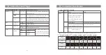
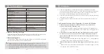
Setting the Flash Trigger
Setting the Flash Trigger
CH1
A
B
C
D
E
--
ON
1
/64
--
--
--
Zm/CH Times
Hz
MOD
3 Times
1 Hz
MULTI
CH1
A
C
D
E
--
M
--
--
1
/64
B
M
1
/64
Gr
Gr
CH1
A
C
D
E
--
M
--
--
1
/64
B
M
1
/64
LOCKED
- 34 -
- 33 -
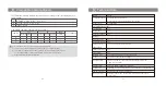
Output Value Settings
1. Multi-group displays in the M mode
1.1
Press the group button to choose the group, turn the select dial, and the power
output value will change from Min to 1/1 in 0.3 or 0.1 stop increments. Press
the <
SET
> button to confirm the setting.
1.2
Press <
ALL
> button to choose all groups’ power output value, turn the select
dial, and all groups’ power output value will change from Min to 1/1 in 0.3 or
0.1 stop increments. Press <
ALL
> button again to confirm the setting.
2. One-group displays in the M mode
Turn the select dial and the group’s power output value will change from Min to 1/1
in 0.3 or 0.1 stop increments.
Note:
Min. refers to the minimum value that can be set in M or Multi mode. The minimum value can be
set to 1/128, 1/128(0.1), 1/256 or 1/256(0.1) according to C.Fn-STEP. For most of camera flashes, the
minimum output value is 1/128 or 1/128(0.1) and cannot be set to 1/256 or 1/256(0.1). However, the
value can change to 1/256 or 1/256(0.1) when using in combination with Godox strong power flashes
e.g. AD600Pro, etc.