background image

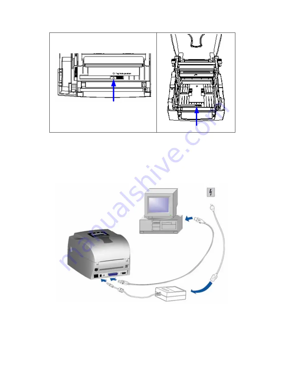
2-4. Card / Hang tags Installation 

When installing cord tags, the tag hole must align 
with the sensor arrow (as indicated in figure), then 
use the Label Guide to secure the tags. 


Sensor Detection Position       


Sensor 

 
2-5. PC Connection 

1. 

Please make sure the printer is powered off. 

2. 

Take the power cable, plug the cable switch to the power socket, and then connect the 
other end of the cable to the printer power socket. 

3. 

Connect the cable to the USB/parallel port on the printer and on the PC. 

4. 

Power on the PC and the printer and the printer’s LED light will shine.     


EZPi-1000 User’s Manual 
 

15

Summary of Contents for EZPi1000 Series

Page 1: ...User s Manual EZPi 1000 Series P N 920 013011 00 Rev B 05 2009 ...

Page 2: ...1998 A1 2000 A2 2003 CISPR 22 Class A EN 55024 1998 A1 2001 A2 2003 IEC 61000 4 Series EN 61000 3 2 2000 EN 61000 3 3 1995 The equipment also tested and passed in accordance with the European Standard EN55022 for the both Radiated and Conducted emissions limits EZPi 1000 SERIES TO WHICH THIS DECLARATION RELATES IS IN CONFORMITY WITH THE FOLLOWING STANDARDS EN55022 1998 CLSPR 22 Class A EN55024 199...

Page 3: ...igkeit in das Gerät gelangen so ziehen sofort den Netzstecker Anderenfalls besteht die Gefahr eines lebensgefährlichen elektrischen Schlags 5 Wartungs und Reparaturarbeiten dürfen aus Sicherheitsgründen nur von autorisierten Personen durchgeführt werden 6 Bei Wartungs und Reparaturarbeiten müssen die Sicherheitsvorschriften der zuständigen Berufsverbände und Behörden unbedingt eingehalten werden 7...

Page 4: ...ossible transient over voltage damage 4 Don t pour any liquid to the equipment to avoid electrical shock 5 ONLY qualified service personnel for safety reason should open equipment 6 Don t repair or adjust energized equipment alone under any circumstances Someone capable of providing first aid must always be present for your safety 7 Always obtain first aid or medical attention immediately after an...

Page 5: ...Control Panel Introduction 18 3 2 Control Keys Introduction 18 3 3 Setting mode 20 3 4 Self Test 25 3 5 Dump Mode 26 3 6 Auto Sensing 26 3 7 Keyboard Mode 27 3 8 Error Messages 30 4 ACCESSORY 32 4 1 Stripper Installation 32 4 2 Cutter Installation 35 4 3 WLAN Module Installation 37 4 4 CF Card Adapter Installation 41 4 5 CF Card Instruction 42 5 MAINTENANCE AND ADJUSTMENT 43 5 1 Thermal Print Head...

Page 6: ... length auto sensing or command settable Media Label Roll O D Max 127mm 5 Core I D 25 4mm 1 38 1mm 1 5 76 2mm 3 Width 25 4mm 1 to 118mm 4 64 Thickness 0 06mm 0 003 to 0 25mm 0 01 Ribbon Length 300M 981ft Max ribbon roll O D 68mm 2 67 Core I D 25 4mm 1 Type transfer ribbons wax hybrid and resin in widths of 30mm to 110mm 1 18 to 4 33 Printer Language EZPL GEPE downloadable Software QLabel IV EZPL o...

Page 7: ...rd with Print Server replace USB port Control Panel Back lit LCD Display 128x64dots Graphic LCD Three LEDs Power Ribbon Media Three control keys FEED PAUSE CANCEL Power Auto Switching 100 240VAC 50 60Hz Environment Operation 41 F to 104 F 5 C to 40 C Storage 4 F to 122 F 20 C to 50 C Humidity Operation 30 85 non condensing Storage 10 90 non condensing Cert Approval CE EMC FCC Class A CB cUL CCC Pr...

Page 8: ...Ground N C Select in host printer host printer printer printer printer host printer host host printer printer host printer Serial Interface Serial Default Setting 9600 baud rate no parity 8 data bits 1 stop bit XON XOFF protocol and RTS CTS RS232 HOUSING 9 pin to 9 pin DB9 SOCKET DB9 PLUG 1 1 5V max 500mA RXD 2 2 TXD TXD 3 3 RXD DTR 4 4 N C GND 5 5 GND DSR 6 6 RTS RTS 7 7 CTS CTS 8 8 RTS RI 9 9 N ...

Page 9: ...D 2 2 RXD RXD 3 3 TXD CTS 4 4 RTS GND 5 5 GND RTS 6 6 CTS E_MD 7 7 E_MD RTS 8 8 CTS E_RST 9 9 E_RST 5V 10 10 5V GND 11 11 GND 5V 12 12 5V UART2 wafer Expansion module 5V 1 1 5V CTS 2 2 RTS TXD 3 3 RXD RTS 4 4 CTS RXD 5 5 TXD GND 6 6 GND EZPi 1000 User s Manual 8 ...

Page 10: ...el Roll Core 4 Ribbon Rewind Wheel 5 LCD Module Case 6 Printing Mechanism 7 Front Cover Piece 1 Ribbon Rewind Shaft Empty Ribbon Roll 2 Locking Tenon left right 3 CF Card Slot Cover 4 Print Head Pressure Adjustment Screw left right EZPi 1000 User s Manual 9 ...

Page 11: ...l Sensor 1 LCD Control Panel 2 Fan Fold Label Insert 3 Connection Port for PS2 Wireless LAN Antenna Optional 4 Power Switch 5 Ethernet Port 6 USB Port 7 Parallel Port 8 Serial Port RS 232 9 Power Socket The communication ports may vary depending on product types EZPi 1000 User s Manual 10 ...

Page 12: ... only requires direct thermal media Please check the specific print mode and then go into the Setting Mode after power on the printer 2 1 Ribbon Installation 1 Place the printer on a horizontal surface and open the top cover by pressing the Cover Open Buttons on both sides 2 Loosen and then lift the upper print mechanism by pressing the locking tenons 3 Place a new ribbon roll onto the ribbon supp...

Page 13: ...bon from the Ribbon Supply Shaft under the Print Head 5 Wrap the ribbon around the Ribbon Shaft and stick the ribbon onto the Empty Ribbon Roll Core 6 Firmly close the upper print mechanism EZPi 1000 User s Manual 12 ...

Page 14: ...op Plates on both sides of label roll 4 Place the label roll into the printer 5 Loosen and lift the upper print mechanism by pressing the locking tenons 6 Feed the label through the two Label Guides to the Tear off Bar 7 Align the label guides to the edge of label 8 Close the upper print mechanism from the top to finish label installation EZPi 1000 User s Manual 13 ...

Page 15: ...2 3 Label Roll Core Installation Instruction A 1 roll core installation B 1 5 roll core installation C 3 roll core installation EZPi 1000 User s Manual 14 ...

Page 16: ...Position Sensor 2 5 PC Connection 1 Please make sure the printer is powered off 2 Take the power cable plug the cable switch to the power socket and then connect the other end of the cable to the printer power socket 3 Connect the cable to the USB parallel port on the printer and on the PC 4 Power on the PC and the printer and the printer s LED light will shine EZPi 1000 User s Manual 15 ...

Page 17: ...s Drives folder 2 Select the icon of driver file and click it to start the installation 3 Follow the instruction on screen to keep the installation going Then the Driver Wizard utility should run automatically 4 Select Install printer drivers 5 Select printer model EZPi 1000 User s Manual 16 ...

Page 18: ...d after all settings are completed 9 Check if all printer settings are correct and then press Finish to start copying driver files 10 Wait for file copying finished and complete the installation 11 After the driver installation is complete there should be a new printer model on Windows Printer and Faxes setting EZPi 1000 User s Manual 17 ...

Page 19: ...r will go into the Pause Mode and LCD Display will indicate EZPi xxxx Vx xxx Pause At this status printer won t be able to receive any command Then pressing the Pause key once again the printer will get out of the Pause mode and go back to standby mode Pressing the Pause key while printing printer will pause the print job When the Pause key is pressed one more time the printer will continue with t...

Page 20: ...Auto sensing Power on 3 beeps Auto sensing Mode Press and hold key and turn on the printer until the buzzer beeps 3 times Go to default Power on 2 beeps twice Go to default Press and hold keys and turn on the printer until the buzzer beeps 2 times The printer setting will go to default Download mode Power on 1 beep DL MODE Vx xx Press and hold key and turn on the printer until the buzzer beeps onc...

Page 21: ...he Setting Mode printer will prompt user whether to save the settings After user s response on whether do or do not save the settings printer will return to standby mode Press and hold key about 3 to 4 seconds until the buzzer beep 3 times and LCD shows Setting mode The LCD monitor will show different options on the bottom After entering to Setting mode the first highlight on LCD monitor indicates...

Page 22: ...ents onto the media Direct Thermal when printing no ribbon is necessary it only requires direct thermal media Option Setup Default Option OFF Strip Mode turn on the stripper function Cutter Mode turn on the cutter function Applicator Mode turn on the applicator function None select this to turn off the stripper and cutter functions Sensor Setup Default Gap paper Black Mark for label or plain paper...

Page 23: ...an Finnish Dutch Belgian Keyboard Mode Default Recall Label Recall Label Recall label from memory card Keyboard Setup Setting the keyboard Code page Setup Setting the code page Printing Option Set the print quantity Clock Setup Set the clock and clock display only effective when optional RTC module is installed Exit KB Mode Exit PS2 KB Mode Buzzer Setup Default ON ON OFF Smart Backfeed Default ON ...

Page 24: ...d check all settings Note 1 Default Setting is the original settings from the factory if other changes are made on the settings then follow the new settings Note 2 Printer will store the previous settings after power off thus if settings are to be changed again please enter the Setting Mode to reset EZPi 1000 User s Manual 23 ...

Page 25: ...arity Data Bits Stop Bits Auto Mode Gap Mode Black Mark Mode English Simplified Chinese Traditional Chinese Code Page 850 Code page 852 US UK French German Spanish Italian Finnish Dutch Belgian Recall Label Keyboard Setup Code page setup Printing Option Clock Setup ON OFF Smart Backfeed ON OFF Password ON OFF D D Exit KB Mode Code Page 850 Code page 852 Darkness 0 19 Speed 2 7 Adjust Stop Position...

Page 26: ...ating normally EZXXXX VX XXX Serial port 96 N 8 1 int usb sw setting ext USB 1 DRAM installed Image buffer size 1500K 000 FORM S IN MEMORY 000 GRAPHIC S IN MEMORY 000 FONT S IN MEMORY 000 ASIAN FONT S IN MEMORY 000 DATABASE S IN MEMORY 000 TTF S IN MEMORY 2048K BYTES FREE MEMORY S4 H19 R000 R200 W100 Q100 3 Option D0 O0 AD See through Volt 4 8 3 7 2 4 2 3 Code Page 850 Model Version Serial port se...

Page 27: ...the print result matches the commands sent To cancel get out of the Dump Mode press the FEED key this time printer will automatically print out OUT OF DUMP MODE This indicates that printer is back in the standby mode Or power off to exit the Dump Mode 3 6 Auto Sensing Printer can automatically detect label black mark paper length and record it By this way without setting the print length the print...

Page 28: ...yboard mode function in setting mode To change the keyboard setting please refer to the Setting Mode diagram in Chapter 3 3 Print a label with stored form in Keyboard Mode FTEST1 Q100 3 W100 H10 P1 S2 AD C1 R0 Q 0 O0 D0 E12 R200 L Dy2 me dd Th m s C0 00001 1 Serial Number V00 16 Product Name jc0 V01 16 Price jc0 AF 330 566 1 1 0 0 C0 AH 212 168 1 1 0 0 V00 AG 308 396 1 1 0 0 V01 E 1 At least one l...

Page 29: ...le 00001 8 LCD will show the first Variable Prompt 9 Key in the variable data Example Apple 10 LCD will show the second Variable Prompt 11 Key in the variable data Example 199 12 LCD shows the Print quantity 13 Key in the print quantity Example 3 EZPi 1000 User s Manual 28 ...

Page 30: ...14 The printer will print out 3 labels that include user defined variables and serial number EZPi 1000 User s Manual 29 ...

Page 31: ... sure the printer is in the Direct Thermal mode Out of ribbon or check ribbon sensor 3 beeps twice Ribbons used up or ribbon supply shaft not moving Replace with new ribbon roll Unable to detect paper Make sure the movable sensor mark is at the correct position if the sensor is still unable to detect paper and then go through Auto Sensing again Out of media or check media gap sensor 1 beep twice L...

Page 32: ...inder is full Remove the labels on rewinder Filename can not be found 2 beeps twice Can t find the file Use X4 command to print out all the files then check whether the file exist and the names are correct Filename repeated 2 beeps twice File name is repeated Change the file name and download again EZPi 1000 User s Manual 31 ...

Page 33: ...be 0 06mm 10 with basic weight 65g 6 Note3 The max width for stripper is 110mm 2 1 1 Open the top cover by pressing the Cover Open Buttons on both sides 2 Loosen and then lift the upper print mechanism by pressing the locking tenons 3 Unlock the front cover piece by pushing locks inward 4 Lift take off the front cover piece according to the direction shown in the figure EZPi 1000 User s Manual 32 ...

Page 34: ...irst 6 Place the left side of the stripper first and then fit the right side 7 Hold the stripper module and tighten the screws 8 Feed the label through the Label Guides Note The label paper used for stripper is suggested to be at least 20mm in height Suggestion When printing with stripper module it is suggested to set the stop position E to 9 9 Peel off the first label and feed the liner through t...

Page 35: ...on as shown in figure to feed the liner across the stripper 11 Close the upper print mechanism and the stripper 12 Press the FEED key to adjust the position of label and complete the installation EZPi 1000 User s Manual 34 ...

Page 36: ...paper cutting width is 116mm Note4 The label paper that used for cutting is suggested to be at least 30mm in height 1 Open the top cover by pressing the Cover Open Buttons on both sides 2 Loosen and then lift the upper print mechanism by pressing the locking tenons 3 Unlock the front cover piece by pushing locks inward 4 Lift take off the front cover piece according to the direction shown in the f...

Page 37: ...se the cutter module 10 Feed the label through the Label Guides 11 Close the mechanism to complete the cutter module installation Note It is not suggested to use label inside paper when printing with cutter module 12 Press the FEED key to adjust the position of label and complete the installation Suggestion When printing with cutter module it is suggested to set the stop position E to 30 EZPi 1000...

Page 38: ...0 Fixture Plate 11 Antenna Bracket 1 Make sure the power is off and the power cable is unplugged Place the printer onto a smooth surface and flip the whole printer unit upside down 2 Unscrew the screws as indicated in figure 3 Press the Cover Open Button and open the top cover 4 Remove the middle compartment and the top cover 5 Unplug the Ethernet Module Connection Wire EZPi 1000 User s Manual 37 ...

Page 39: ...nd Wire Screw and unplug the connection wire of PS2 Port to remove the PS2 Port 10 Tighten the Ground Wire Screw 11 Secure the WLAN module onto the bracket 12 Cut the cable tie on the Module Connection Wire Then Plug the connector into the socket on WLAN module Note Please cut the cable tie carefully Do not damage the Module Connection Wire EZPi 1000 User s Manual 38 ...

Page 40: ...in figure Then arrange the Antenna Connection Wire as the arrow showed Note Please organize all cables and wires well before putting middle compartment and top cover back to ensure that the printer can be assembled correctly 16 Thread Antenna Connection Wire through the hole on the Antenna Bracket Then put the Antenna Connection Wire and Antenna Bracket on the Antenna port as figure showed EZPi 10...

Page 41: ...eded 19 To complete the installation reassemble the middle compartment and tighten the screws onto the bottom of the printer then put the top cover back Note 1 After the WLAN module installation is completed please send the XSET USBETHERNET 1 printer command to printer for activating the Ethernet connection function Please mind that USB port will be deactivated once the Ethernet connection functio...

Page 42: ...over by pressing the Cover Open Buttons on both sides 2 Take off the label roll core 3 Open and remove the plastic cover from the inner base 4 Check the correspondent pins and sockets to plug the adapter card onto the main board Note Please make sure the sockets and the pins are match otherwise the pins may get damaged 5 Close the plastic cover EZPi 1000 User s Manual 41 ...

Page 43: ...ed in FAT16 it will beep 3 times and the Status led light will flash orange 3 If user wants to format the CF Card just press the FEED key and then the printer will start to format the CF Card in FAT16 When the format is complete the LED light will turn to green 4 If choose not to format the CF Card just open the Top Cover of printer and wait for the turn on procedure complete 5 After the format is...

Page 44: ...ee blue arrow there s label pieces or other stain please use a soft cloth with industrial use alcohol to wipe away the stain Note1 Weekly cleaning on the print head is recommended Note2 When cleaning the print head with soft cloth make sure there is no any metal or hard particles attached on it 5 2 Thermal Print Head Balance Adjustment When printing with different label materials or using differen...

Page 45: ... as arrow 2 shows print head would move in the direction where arrow B shows A B 1 2 5 4 Adjust the cutter 1 A cutter adjusting hole is present on the side of cutter where A is pointing to 2 The cutter will not work properly if there is a paper jam Turn the power off and use a M3 hexagon wrench inserted into hole A and then turn it counter clockwise 3 Power on the printer after clearing the paper ...

Page 46: ...laten roller If the platen roller needs to be replaced please contact your reseller for more information Check if power supply is correct When printing part of the label wasn t printed completely Check if Thermal Print Head is stained or dusted Use internal command T to check Thermal Print Head can print completely Check the media quality Printout not in desired position Check if sensor is covered...

Reviews: