


33
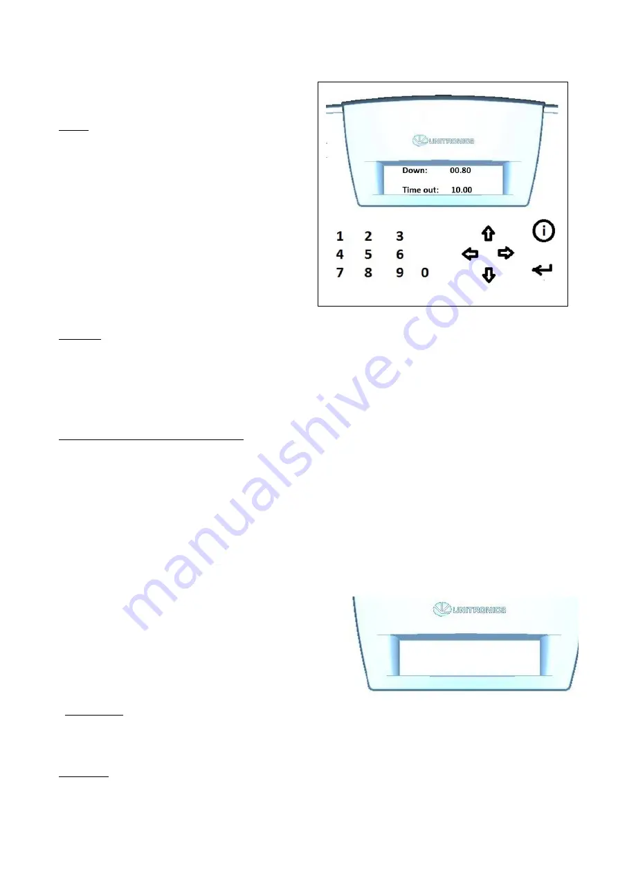
5.3.5 The “SERVIS1” menu
Image 1: in this menu you set 2 key
parameters.
Down
The time in seconds during which the applicator
head travels and remains down before returning
to its starting position.
In workflows in which objects of various sizes
are handled simultaneously this value must be
adjusted to the objects that require the
longest travelling time.
In case all objects require the same travelling
time the distance to the applicator base plate
can be minimized and with it the travelling
time. This ensures the highest possible system
speed.
Time out
This value in seconds determines the maximum duration of one application cycle. If a cycle has
not been completed within this length of time the system will go into error mode.
This function will stop the system if an error occurs after the initialization of an application cycle
and the cycle cannot be completed. Possible examples are the applicator head being
obstructed and lack of feedback from the printer.
Selecting and setting the parameters
1) The „DOWN“ value will be blinking automatically. Either change and confirm or only confirm
the pre-selected value with the „enter“ key. The cursor will jump to the „TIME OUT“ value.
2) Change and confirm or only confirm the pre-selected „TIME OUT“ value with „enter“. Exit menu
“SERVIS1”
Push the “START” button to return to the “START” menu Select the DOWN-arrow to go to the
“MANUAL menu
5.3.6 The “MANUAL” menu
Image 1: this menu is used to test individual
stages of the print&apply process. Can only
be used with the system in “STOP” mode. It is
not possible to test a full cycle in this menu.
Options are selected on the numeric keypad.
Select “1” to check the airflow through the
little tube underneath the print head. This
airflow blows the label towards the applicator
head.
Select “2” to check whether the applicator head vacuum works well.
MANUAL
1 x 2 x 3 x 4 x
Summary of Contents for AG3000
Page 28: ...28 Pic 7 select the icon shown below to return to main menu Pic 8 Back on main menu ...
Page 36: ...36 Pictures 2 Picture 3 ...
Page 43: ...43 10 Wire diagrams 10 1 Power and signals schematic 10 2 Control unit picture ...
Page 44: ...44 10 3 Power circuits 10 4 Connector rack detailed view ...
Page 45: ...41 10 5 Connector rack diagram ...
Page 46: ...42 10 6 Electro pneumatic diagram 10 6 PLC Printer applicator port diagram ...


