19
Installing the applicator interface
The GoDEX ZX1X00i applicator interface can be used with both 24V and 5V peripheral systems,
both in terms of power supply and in- and outgoing signals. Hence, the correct voltage levels of
the in- and outgoing signals must be configured before installation in the printer. Even in case the
interface board has been pre-configured you
must
verify the setup is correct. You may need to
(re)configure the board to be compatible with the AG3000. The AG3000 requires the 24Volt
configuration.
A wrong configuration may damage your equipment!
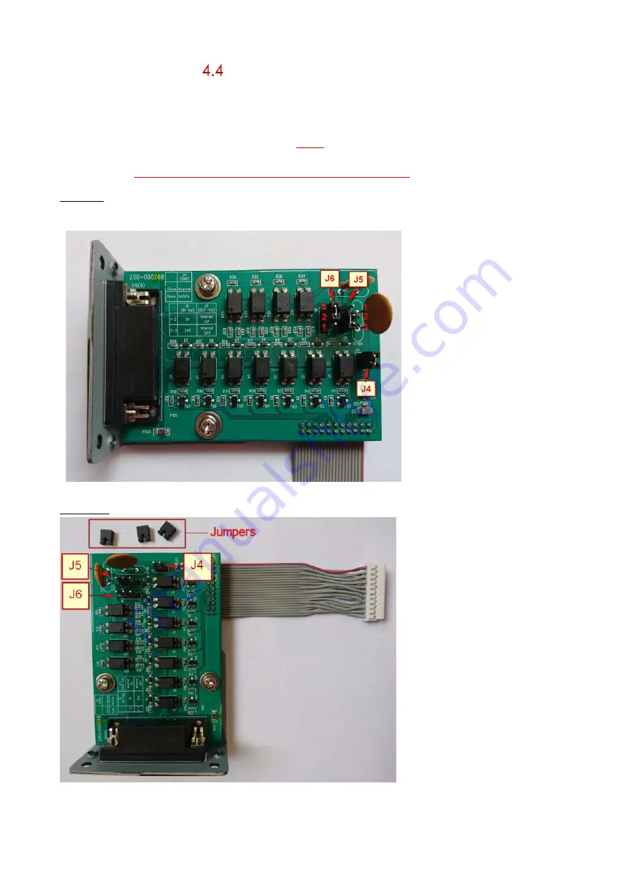
Picture 1: check whether the configuration of the applicator interface board is set correctly for use
with the AG3000 applicator series. Adjust it if necessary. Picture 1 shows the correct configuration.
A.
The two pins on J4
must be connected.
B.
Pin 2 and 3 on J5
must be connected.
C.
Pin 2 and 3 on J6
must be connected.
Pic. 1
Picture 2: the applicator interface board with the three loose jumpers and mainboard flat cable.
Pic. 2
Summary of Contents for AG3000
Page 28: ...28 Pic 7 select the icon shown below to return to main menu Pic 8 Back on main menu ...
Page 36: ...36 Pictures 2 Picture 3 ...
Page 43: ...43 10 Wire diagrams 10 1 Power and signals schematic 10 2 Control unit picture ...
Page 44: ...44 10 3 Power circuits 10 4 Connector rack detailed view ...
Page 45: ...41 10 5 Connector rack diagram ...
Page 46: ...42 10 6 Electro pneumatic diagram 10 6 PLC Printer applicator port diagram ...


