G.M. International ISM0361-3
D5212
- SIL 2 Quadruple Repeater Power Supply
7
Configuration parameters:
Screenshots:
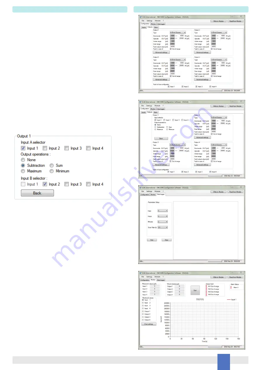
The SWC5090 is able to continuously scan the module and display the real-time values
on screen. Note that while the module is being monitored, configuration screens are
disabled.
The display shows all the monitored parameters:
Input: represents the value read from field.
Output: represents the theoretical output value.
Alarm status: is represented by a led, which is red when activated.
Faults: is represented by a led, which is red when activated
Graph: shows only the variable chosen from the monitored values box.
INPUT:
Out of range:
Low threshold: input value below which the fault is triggered
High threshold: input value above which the fault is triggered
Tag:
16 alphanumerical characters
OUTPUT:
Type:
0-20 mA Source
4-20 mA Source
Custom Source
all output parameters are fully customizable
Downscale:
analog output downscale in normal working condition (range 0 to 24 mA)
Upscale:
analog output upscale in normal working condition (range 0 to 24 mA)
Under range:
analog output value in under range condition (range 0 to 24 mA)
Over range:
analog output value in over range condition (range 0 to 24 mA)
Fault output value:
analog output value in case of fault condition (range 0 to 24 mA)
Fault in case of:
analog output is forced to “Fault Output Value” when input is out of
configured range
Advanced settings:
When the advanced settings button is clicked, the following
settings box is shown.
Input A selector:
Input 1: output represent Input1
Input 2: output represent Input2
Input 3: output represent Input3
Input 4: output represent Input4
Output operations:
None:
output operations are disabled.
Subtraction: analog output represents the subtraction of the two selected
input channels.
Sum:
analog output represents the sum of the two selected input channels.
Maximum: analog output represents the higher of the two selected input ch.
Minimum: analog output represents the lower of the two selected input channels.
Input B selector:
(it is shown when the output operations selected is not None)
Input 1: represents the second operand used for the output operation.
Input 2: represents the second operand used for the output operation.
Input 3: represents the second operand used for the output operation.
Input 4: represents the second operand used for the output operation.
Monitor
Data logger Configuration
Output Configuration
Output Advanced


