


2 Notes on the documentation
6
Installation and maintenance instructions Energy 0020201109_01
2
Notes on the documentation
2.1
Observing other applicable documents
▶
You must observe all the operating and installation in-
structions included with the system components.
2.2
Storing documents
▶
Pass these instructions and all other applicable docu-
ments on to the system operator.
2.3
Applicability of the instructions
These instructions apply only to:
Models and article numbers
Great Britain
Ireland
Energy 35 Store-A
0010017338
0010017338
The designation -A indicates that the product is equipped
with a pneumatic gas valve.
3
Product description
3.1
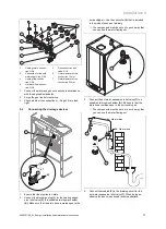
Serial number
1
The serial number is located on the identification plate
(1)
.
3.2
Gas Council number
Energy 35 Store-A
G.C. no. 47-019-37
3.3
Information on the identification plate
The identification plate is attached to the product at the fact-
ory.
The identification plate indicates the country in which the
product is to be installed.
Information on the
identification plate
Meaning
Barcode with serial number
Information on the
identification plate
Meaning
Serial number
For quality control purposes; 3rd and 4th
digits = year of production
For quality control purposes; 5th and 6th
digits = week of production
For identification purposes; 7th to 16th
digits = product article number
For quality control purposes; 17th to 20th
digits = place of manufacture
Energy 35 Store
Product description
2H / 2E / 3P / 2L...
Gas group and gas connection pressure
as set at the factory
II2H3P / I2E / I3P...
Approved gas category
Condensing techno-
logy
Efficiency class of the boiler in accord-
ance with EC Directive 92/42/EEC
Type: Xx3(x)
Permissible flue gas connections
PMS
Maximum water pressure in heating
mode
PMW
Maximum water pressure in hot water
handling mode
V
Hz
Electric connection
H
i
Lower gross calorific value
W
Max. electrical power consumption
IP
Protection class
Heating mode
Hot water generation
P
n
Nominal heat output range in heating
mode
P
Nominal heat output range in hot water
handling mode
P
nc
Nominal heat output range in heating
mode (condensing technology)
Q
n
Nominal heating load range in heating
mode
Q
nw
Nominal heating load range in hot water
handling mode
NOx
NOx class for the product
Code (DSN)
Specific product code
→
"CE label" section
Read the instructions.
→
"Recycling and disposal" section
GC no.
Gas council number


