


Adjusting the hot water temperature 8
0020201109_01 Energy Installation and maintenance instructions
21
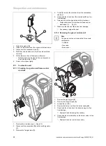
7.3
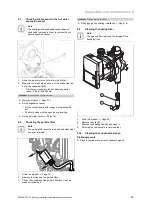
Setting the bypass valve
1
▶
Turn the adjusting screw
(1)
.
–
Setting the bypass valve in the as-delivered condition:
Open by 3/4 of a turn.
8
Adjusting the hot water temperature
Danger!
Risk of death from Legionella.
Legionella multiply at temperatures below
60 °C.
▶
Ensure that the operator is familiar with all
of the Anti-legionella measures in order
to comply with the applicable regulations
regarding legionella prevention.
9
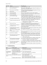
Inspection and maintenance
9.1
Observing inspection and maintenance
intervals
▶
Comply with the minimum clearances for the inspection
and maintenance. Depending on the results of the in-
spection, it may be necessary to bring maintenance work
forward.
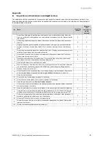
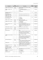
Inspection and maintenance work
–
Overview
9.2
Procuring spare parts
The original components of the product were also certified
as part of the declaration of conformity. If you do not use
certified Glow-worm original spare parts for maintenance
or repair work, this voids the conformity of the product. We
therefore strongly recommend that you install Glow-worm
original spare parts. Information about available Glow-worm
original spare parts is available by contacting the contact
address provided on the reverse of this document.
▶
If you require spare parts for maintenance or repair work,
use only Glow-worm original spare parts.
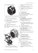
9.3
Gas conversion procedure
1
1.
Disconnect the product from the power mains.
2.
Turn the bolt
(1)
in the direction specified in the table
and by the number of rotations specified in the table.
Setting the gas valve
Turning
clockwise
Turning
anti-clock-
wise
G20
→
G31
G31
→
G20
Energy 35 Store-
A
2.5
2.5
3.
Start up the product with the check programme
(P.01)
and set the value.
–
Setting value for the programme P.01: 100
Check programmes
–
Overview (
→
Page 28)
Note
If the product is in the operating cycle
(ON/OFF), decrease the set value.
4.
Wait until the value that is read is stable.
–
Waiting period for reading a stable value: 2 min
5.
Measure the CO
₂
content at the flue gas analysis point
(2)
.
6.
Compare the measured value with the corresponding
value in the table.
Checking the CO
₂
content
Great
Bri-
tain
Removed
front casing
Natural gas
G20
9
±
0.2 %
Liquid gas
G31
10.1
±
0.2 %
Fitted front
casing
Natural gas
G20
9.2
±
0.3 %
Liquid gas
G31
10.3
±
0.3 %
▽
Set the CO
₂
(
→
Page 19) content as required.


