


Start-up 6
0020201109_01 Energy Installation and maintenance instructions
17
1
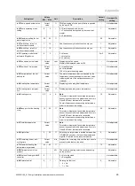
1.
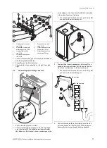
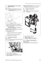
Open the purging valve cap
(1)
on the pump and on the
automatic air vents.
2.
Fill the system with water until the filling pressure is
reached.
–
Recommended filling pressure: 1 … 1.5 bar
(100,000 … 150,000 Pa)
◁
The programme for automatic purging starts as
soon as the pressure warning value is reached.
–
Pressure warning value:
≤
0.5 bar
(
≤
50,000 Pa)
–
Automatic purging time: 5 min
◁
The heating and hot water functions cannot be activ-
ated.
3.
Purge each radiator until the water escapes normally,
and then close the system's purging valves.
Note
Leave the cap on the pump's purging valve.
4.
Ensure that the hot water pressure is in the recommen-
ded range.
▽
If required, refill the product.
5.
Check that all connections are leak-tight.
Conditions
: If the noise persists in the boiler
▶
Purge the product again by activating check programme
(P.07)
and then
(P.06)
.
Check programmes
–
Overview (
→
Page 28)
6.9
Building up pressure in the system again
1.
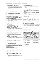
Run the product in heating mode with a sufficiently high
target heating temperature.
–
Product operating period:
≥
15 min
Target heating temperature
Conditions:
Heating system with
high-temperature radiators
≥
50
℃
Conditions:
Heating system with
low-temperature radiators
OR Heating system with floor-
standing heating
≤
50
℃
2.
Purge each radiator until the water escapes normally,
and then retighten the system's purging valves.
Conditions
: Difficulty purging the heating circuit
▶
Start the check programme
(P.06)
.
Check programmes
–
Overview (
→
Page 28)
3.
Check the filling pressure.
–
Recommended filling pressure: 1 … 1.5 bar
(100,000 … 150,000 Pa)
▽
If required, refill the product.
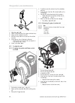
6.10
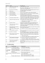
Checking and adjusting the gas ratio
setting
1
Only one competent person is authorised to implement the
settings on the gas valve.
Each destroyed seal must be restored.
The CO
₂
adjusting screw
(1)
may have to be sealed after a
gas conversion.
Any interference with the gas valve's adjusting screw Offset
(zero point setting) is not permitted (the screw is sealed with
leads after setting ex works).
6.10.1 Checking the leak-tightness of the flue gas
system and for flue gas recirculation
1.
Check that the flue gas system is intact, in accordance
with British Gas TB 200.
2.
If the flue gas installation is longer than 2 m, a flue gas
recirculation test is strongly recommended. This test
must be carried out in accordance with the instructions
below.
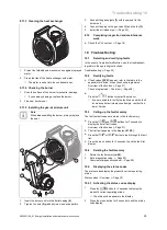
3.
Use the air analysis point
(1)
to check for flue gas recir-
culation.
4.
Use the flue gas measuring instrument.
5.
If you discover CO or CO2 in the fresh air, search for a
leak in the flue gas system or for the flue gas recircula-
tion.
6.
Eliminate the damage.
7.
Repeat the above-mentioned test to determine if the
fresh air contains CO or CO2.
8.
If you cannot eliminate the damage, you must not start
up the boiler.


