Glow-worm economy plus c 30 Instructions For Use, Installation & Servicing Download Page 11

11

221460C

4 Installation

4.3 Gas and Water Connection

Connect the gas supply to the Rc

1

/

2

in gas cock.

The whole of the gas installation, including the meter, should be
inspected, tested for soundness and purged in accordance with
the current issue of BS6891.

Connect the water to the boiler, using nuts and olives supplied,
to BS2871 copper tube.
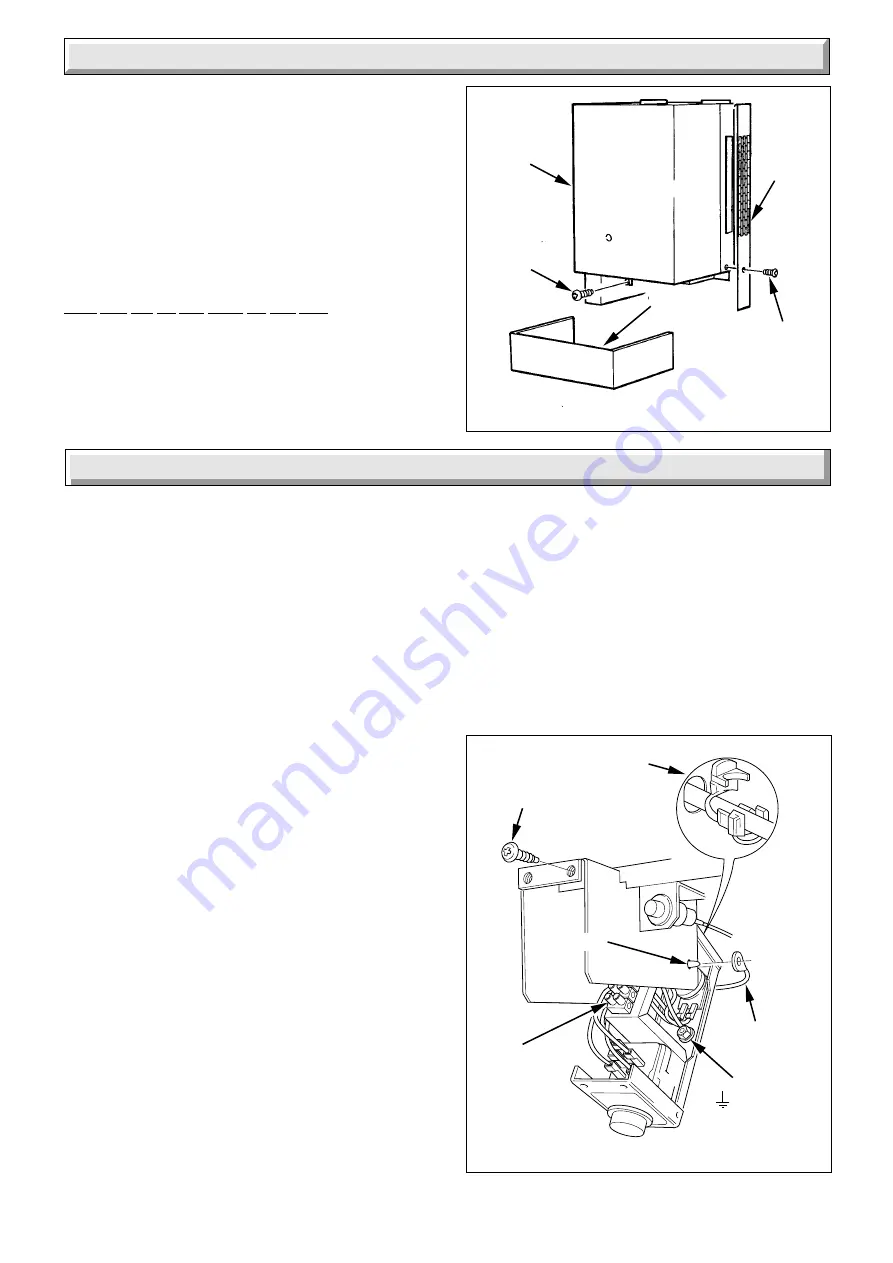
4.4 Casing

Refit the outer casing by hooking on at the top and securing with
the screws previously removed, see diagram 4.1.

Make sure that the side grilles are kept clear.

Diagram 4.1

APPLIANCE PREPARATION

CONTROL
COVER

SECURING
SCREW

SIDE
GRILLE

OUTER
CASE

2410

SECURING
SCREW

5.1 Electrical Connection

WARNING.  The boiler must be earthed and have a permanent
mains supply.

To remove the control box release the two screws at the front,
see diagram 5.1, lower the box until it is clear then push
backwards to disengage the hinge at the rear, see diagram 5.1.
Take care not to damage the thermostat and capillaries.

Thread the mains lead through the clamp in the rear of the
control box cover and connect to the terminal strip.

The mains cable outer insulation must not be cut back external
to the cable clamp.

When making connections, make sure that the earth conductor
is made of a greater length than the current carrying conductors,
so that if the cable is strained the earth conductor would be the
last to become disconnected.

5.2 Pump and External Controls Connections

The pump must be wired into the boiler control box as shown in
diagram 5.2.

Any external controls must only be wired to interrupt the Red link
between terminals 9 and SL.

Take the strain relief grommets from the loose items pack.

Place around the external controls and pump connection cables
respectively.

Squeeze the sides of the grommets when pushing them into the
obround holes in the rear of the control box, see diagram 5.1.
Make sure the supply cable and all external cables are secured.

Diagram 5.1

CONTROL BOX

SECURING
SCREWS

EARTH
POST

TERMINAL
STRIP

RETAINING
STRAP

FASTENER

5352

STRAIN
RELIEF
GROMMET

5.3 Testing - Electrical

Checks to ensure electrical safety should be carried out by a
competent person.

After installation of the system, preliminary electrical system
checks as below should be carried out.

1.  Test insulation resistance to earth of mains cables.

2.  Test the earth continuity and short circuit of all cables.

3.  Test the polarity of the mains.

The installer is requested to advise and give guidance to the
user of the controls scheme used with the boiler.

5 Electrical Wiring

Summary of Contents for economy plus c 30

Page 1: ...Customer Service number 01773 828100 Our Guarantee gives you peace of mind plus valuable protection against breakdown by covering the cost of Guarantee Registration Open Flue Boiler This is a Cat I2H...

Page 2: ...uels 2 Directive 73 23 EEC on the harmonization of the Laws of the Member States relating to the electrical equipment designed for use within certain voltage limits 3 Directive 89 336 EEC on the appro...

Page 3: ...freezing up If an immersion heater is fitted in the domestic hot water cylinder make sure that it is switched off If you have a sealed water system you should contact your installer servicing company...

Page 4: ...ckage safety device may also need resetting refer to safety device instructions Make sure that the pilot is alight and stable Switch on the electrical supply to the boiler Check that all external cont...

Page 5: ...ons applicable in Scotland local Water Company Byelaws The HealthandSafetyatWorkAct ControlofSubstancesHazardous to Health The Electricity at Work Regulations and any local applicable regulations Deta...

Page 6: ...VC flexible type to the current issue of BS6500 Table 16 not less than 0 75mm2 24 0 20mm 1 9 Draining Tap A draining tap must be provided at the lowest points of the system which will allow the entire...

Page 7: ...moval of the boiler Where the boiler is fitted in a cupboard or compartment permanent high and low level ventilation must be provided The minimum ventilation areas required are given in Table A 2 2 Bo...

Page 8: ...ations for the best product to use When installing a boiler in an existing system whether or not using an inhibitor take special care to drain the entire system including the radiators then thoroughly...

Page 9: ...em that is the height of the highest point of the system above the expansion vessel The water capacity of the boiler is given in Section 1 3 7 Pressure Gauge A pressure gauge with a set pointer and co...

Page 10: ...the domestic hot water cylinder Alternatively provision for make up can be made by using a filling loop 3 10 Filling a Sealed Water System Provision for filling the system at low level must be made T...

Page 11: ...cable clamp When making connections make sure that the earth conductor ismadeofagreaterlengththanthecurrentcarryingconductors so that if the cable is strained the earth conductor would be the last to...

Page 12: ...N L N BROWN BLUE GRN YEL GAS VALVE BROWN BROWN RED RED PURPLE BLUE BROWN BLUE GRN YELLOW CHASSIS EARTH POST 3 7 6 8 9 Remove Red Link between 9 and SL when fitting a time control etc If link is not re...

Page 13: ...R BUTTON G VIEWING WINDOW H GAS RATE ADJUSTMENT SCREW UNDER COVER SCREW J GAS SERVICE COCK K PRESSURE TEST POINT L PILOT BURNER ADJUSTMENT SCREW M FLUE BLOCKAGE SAFETY DEVICE RESET SWITCH M Diagram 6...

Page 14: ...ice or replacing parts isolate the gas and electrical supplies Unless stated otherwise all parts are replaced in the reverse order to removal 7 1 Heating Body Service Remove the controls cover by pull...

Page 15: ...ctor manifold Diagram 7 2 ACCESS FOR SERVICING Diagram 7 3 PILOT ASSEMBLY PILOT INJECTOR ADAPTOR OLIVE PILOT TUBING NUT THERMOCOUPLE NUT IGNITION LEAD clear end ELECTRODE THERMOCOUPLE SECURING SCREWS...

Page 16: ...ownindiagram 7 7 Check the pilot burner flame lengths are as shown in diagram 7 7 7 5 Thermocouple Generally follow the instructions given in Section 7 1 Unscrew the thermocouple nut to release from t...

Page 17: ...ithdraw the phial see diagram 7 8 Remove the control box by undoing the two fixing screws at the front and lower the front of the box until it is clear of the cover Push the box towards the rear of th...

Page 18: ...ew s Inset B Carefully remove phial and capillary through back of boiler Inset C Having opened control box remove the electrical connections from the flue blockage safety device the locknut and capill...

Page 19: ...on maximum control thermostat setting Change faulty overheat cutoff device The correctly set overheat cutoff device operates prematurely There is no air in the heating body and water circulation satis...

Page 20: ...continuity YES NO NO 8 7 Thermocouple and Overheat Cutoff Device To test the thermocouple a meter with a range of 0 to 30 mV is required Symptom The pilot burner fails to stay alight Test the thermoc...

Page 21: ...Device if faulty repair or renew Turn ON thermostat Does main burner light Turn ON thermostat With appliance cold Is there 240V between 7 and N Turn ON thermostat Is there 240V between 7 and N MAIN T...

Page 22: ...ONTROLS IN ORDER Faulty Cable PURPLE between thermostat and terminal block repair or renew Faulty pump inform customer Faulty thermostat renew YES YES YES NO NO NO YES Continued Continued MAIN TERMINA...

Page 23: ...TISFACTORY Does pilot flame envelop thermocouple Check aeration If necessary Clean pilot rectify blockage in pilot injector or replace Check thermocouple circuit using Thermocouple and Boiler Overheat...

Page 24: ...cutoff device 313 064 5 800015 Gas valve assembly inc 14 313 067 6 900000 Thermocouple 394 162 7 203415 Pilot burner inc 12 394 161 8 202600 Electrode 384 149 9 416144 Control thermostat knob 355 401...

Reviews: