Global Power Technologies
CATHODIC PROTECTION INTERFACE OPTION
05585 rev11 | Model 8550-SD
Page 48 of 53
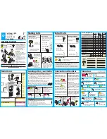
load based on site requirements. See Figure 30 for series connection and Figure 31 for parallel
connection.
9.3.1
SERIES
The CP Interface panel is wired in Series configuration by default from the factory. By connecting the
1000-Watt resistor in series with the CP load, the maximum allowable power may be delivered to the
CP load. This is achieved by moving the tap to the left side of the resistor. To reduce power to the CP
load, slide the tap to the right.
9.3.2
PARALLEL
By connecting the 1000-Watt resistor parallel to the TEG, smaller levels of power may be delivered to
the CP load. This is sometimes required to reduce hot spots on the anode. With the tap located at the
right side of the resistor the output power will be zero. As the tap is moved to the left the power to
the CP load is increased.
The change from series to parallel configuration is made by moving the wire coming from the right
side of the 1000-Watt resistor, from the left position to the center position of the heavy-duty
terminal block.
CAUTION!
For further information on Cathodic Protection applications, please contact Global
Power Technologies
Figure 27 – Parallel Connection
Figure 26 – Series Connection