Global Specialties PB-503A User Manual Download Page 7

globalspecialties.com

Global Specialties

7

 451-032-001_rA

Compliance and Certifications

This product meets the essential requirements of the applicable European Directives as 

follows:

CE Compliance

This product is subject to Directive 2012/19/EU of the European Parliament 

and the Council of the European Union on waste electrical and electronic 

equipment (WEEE), and in  jurisdictions adopting that Directive, is marked as 

being put on the market after August 13, 2005, and should not be disposed 

of as unsorted municipal waste. Please utilize your local WEEE collection 

facilities in the disposition of this product.

*Applicable in the European Union and other European countries with separate collection   

systems.

• 

2014/30/EU: Electromagnetic Directive (EMC)

• 

2014/35/EU: Low Voltage Directive (LVD)

• 

Standard IEC 61010-12011/65/EU + AMD2015/863: Reduction of 

Hazardous Substances Directive (RoHS 2) ANNEX III Exemption 6(c)

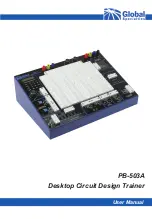
The PB-503A Circuit Design Trainer is a versatile, time-saving tool for circuit designers,       

engineering technicians, students, and hobbyists. A large breadboard area and a wide choice 

of built-in circuit accessories allow rapid and accurate construction of virtually any type of 

analog or digital circuit.

Circuit power is provided by three power supplies, two variable and one fixed. The circuit 

breadboard area includes over 2500 contact points. A multiple-waveform digital function 

generator supplies sine, triangle, and square wave output for analog circuits. A built-in speaker 

may be used for analog output.

Outputs also include a TTL-level square wave generator, two debounced pushbutton switches, 

and a bank of eight logic switches. Eight logic indicators may be used to display high and low 

logic levels. Two built-in potentiometers and two SPDT switches are provided for circuit control 

and adjustment. Connections to external test equipment or signal sources may be made using 

the two BNC connectors on the front panel.

Introduction

Disposal*

Summary of Contents for PB-503A

Page 1: ...User Manual PB 503A Desktop Circuit Design Trainer...

Page 2: ...Components and Features 11 12 Specifications 13 14 Checking out the PB 503A 15 16 Breadboarding Techniques 17 Warranty and Service Information 18 2022 Global Specialties All rights reserved Unauthori...

Page 3: ...witch on the trainer Power off This is the AC mains connect disconnect switch on the trainer This symbol is used to denote an AC signal This symbol is used to denote the chassis ground This symbol is...

Page 4: ...to comply with these precautions or with warnings elsewhere in this manual violates the safety standards of design manufacture and intended use of the instrument Global Specialties assumes no liabili...

Page 5: ...able may result in injury or death Unless otherwise stated a ground connection on the instrument s front is for a reference of potential only and is not to be used as a safety ground This instrument i...

Page 6: ...ith the power cord removed dangerous voltages may exist when the covers are removed To avoid injuries always disconnect the power cord from the instrument remove all other connections for example test...

Page 7: ...ve RoHS 2 ANNEX III Exemption 6 c The PB 503A Circuit Design Trainer is a versatile time saving tool for circuit designers engineering technicians students and hobbyists A large breadboard area and a...

Page 8: ...luable hands on breadboarding techniques and build a solid foundation in circuit experimentation construction and analysis Experienced designers will find the PB 503A an invaluable instrument providin...

Page 9: ...eries Circuits Logic Gates Boolean Algebra Parallel Circuits Combinational Logic Circuits Combinational Circuits Flip Flops Current Control Digital Arithmetic Closed open shorts Counters Registers Swi...

Page 10: ...omes standard with a 250 V 1 5 A type T fuse for the 115 VAC setting In order to use with 230 VAC please slide the switch in the back to 230 VAC and replace the fuse with a 250 V 0 75 A type T fuse AC...

Page 11: ...sition or 70 of the operating voltage or higher when in the CMOS position The green LEDs will light when the voltages at the inputs are 0 8 V or less when in the TTL position or 30 of the operating vo...

Page 12: ...may be connected to other pieces of equipment via two BNC connectors This allows the use of shielded cable to minimize noise and interference Switches Two single pole double throw SPDT switches are pr...

Page 13: ...t circuit protected Output Impedance 600 except TTL Output waveforms Sine Square Triangle TTL Sine Wave Distortion 3 1 kHz typical TTL Pulse Rise fall time 25 ns drives 100 TTL Loads Square Wave Rise...

Page 14: ...s F2 1 k and 10 k uncommitted Speaker 8 0 25 W uncommitted Breadboards Removable breadboard Plate PB 3 with 2520 tie points with 200 additional bus strip tie points internally connected to power suppl...

Page 15: ...are taped together in small batches Removing the components from the tape does not always remove the adhesive from the leads of the components Placing a formerly taped component into a socket connect...

Page 16: ...relationship between the switch positions and the logic indicator display should remain the same regardless of the setting of the 1 3 15 volts V supply By using an ohmmeter you can check the potentiom...

Page 17: ...s Sometimes the only way to correct high frequency circuit problems is to shorten all circuit connections Be especially careful when inserting integrated circuits into the breadboard sockets Unless th...

Page 18: ...ot be covered by this warranty Global Specialties reserves the right to discontinue models change specifications price or design of this device at any time without notice and without incurring any obl...

Page 19: ...19 globalspecialties com Global Specialties...

Reviews: