


15
q
9) Mix up a small amount of Kwik Bond 5
Minute Epoxy. Using a toothpick, pack epoxy into
the hole. Rotate the tiller arm so the slot in the arm is
even with the hole in the bottom of the rudder.
q
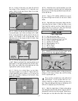
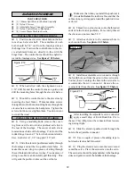
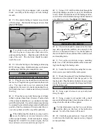
10) Insert the 2mm x 40mm wire pin through the
slot and into the hole. The wire should extend about
7/8” beyond the bottom edge of the rudder. Allow the
epoxy to fully cure. See photo # 24 below.
Photo # 24
q
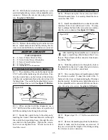
11) Loosen the machine screw in the side of the
tiller arm and align the tail wheel wire with the rud-
der. When satisfied with the alignment, tighten the
machine screw securely.
INSTALLING THE TAIL WHEEL
q
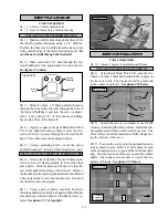
12) Install the 25mm diameter tail wheel onto
the tail wheel wire. Secure the tail wheel in place
using one 2mm wheel collar and one 2mm x 5mm
machine screw. Slide the wheel collar on enough so
it is up against the tail wheel, but not so tight that the
tail wheel won't turn. The tail wheel should rotate
without binding.
PARTS REQUIRED
q
{2} Nylon Motor Mount Beams
q
{4} 4mm x 20mm Machine Screws
q
{4} 4mm x 35mm Machine Screws
q
{8} 4mm Flat Washers
q
{4} 4mm Split Washers
q
{4} 4mm Hex Nuts
q
{4} 4mm Blind Nuts
ENGINE INSTALLATION
ENGINE INSTALLATION OPTIONS
Several options can be used for the engine and
style of installation you choose. For two cycle
engines, we recommend a .40 - .53 displacement en-
gine mounted sideways. The Skyraider will accept a
two cycle engine with a stock muffler, but trimming
of the cowl to fit the muffler will be necessary. For a
cleaner and more scale appearance the use of an in-
cowl Pitts style muffler, compatible with the engine
you're using, is highly recommended.
For four cycle engines we recommend a .60 - .80 dis-
placement engine mounted inverted. This is a very
clean installation and use of an in-cowl muffler is un-
necessary. The exhaust can simply be directed out
the bottom of the cowling. Which ever system you
choose, the following assembly steps layout the spe-
cific crankshaft location for both two cycle and four
cycle engines. Engines are mounted with 0º thrust.
q
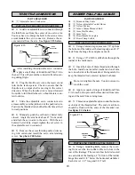
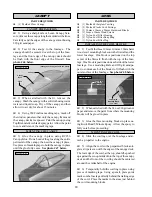
1) Use a clamp and a spacer to hold the two
mounting beams together. The beams should be level
with each other and parallel. The predrilled mount-
ing holes are not the same distance from the beam
surface. The engine should be mounted on the "tall"
side of the beams. See photo # 25 below.
Photo # 25
q
2) Mark the locations of the four engine mount-
ing holes on the beams using a pencil. For the engine
to align properly with the front of the cowling, it is
important that the front edge of the engine's drive
washer be 4-1/2” forward back surface of the mount-
ing beams.
q
3) When satisfied with the alignment of the en-
gine, remove the beams from the clamp and drill 3/32”
pilot holes through the mounting beams at the four
engine mounting hole locations. Double check the
alignment of the engine and then drill out the holes
through the beams using a 5/32” drill bit.
q
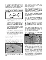
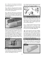
4) Mount the engine to the mounting beams us-
ing the four 4mm x 35mm machine screws, four 4mm
flat washers, four 4mm split washers and four 4mm
hex nuts. The flat washers and split washers are in-
stalled on the bottom of the beams only. Tighten the
screws and nuts completely. See photo # 26 below.
Photo # 26
INSTALLING THE ENGINE TO THE MOTOR MOUNT
For both 2 cycle and 4 cycle engines
Tiller
Arm
Wire
Pin
Spacer
Motor
Mount
Beams
Clamp


