


13
q
7) On the top and bottom of the stabilizer, draw
a line where it and the fuselage sides meet. Do this
on both the right and left sides.
q
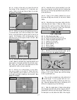
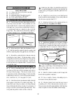
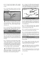
8) Remove the stabilizer. Using the lines you
drew as a guide, remove the covering from between
them using a modeling knife. See photo # 20 below.
Photo # 20
When using the modeling knife, be careful not to
cut too deep. Only use enough pressure to cut
the covering. Cutting deeper into the wood can weaken
the structure and cause the stabilizer to fail in flight.
q
9) When you are sure that everything is aligned
correctly, glue the horizontal stabilizer in place using
Kwik Bond 30 Minute Epoxy. Double check all of
your measurements once more before the epoxy cures.
Wipe away any excess epoxy using paper towels and
rubbing alcohol and hold the stabilizer in place using
masking tape or T-pins.
Because the stabilizer has to slide in place
through the fuselage, we suggest you apply a
liberal amount of epoxy to only the gluing surface of
the stabilizer. This will prevent spreading epoxy over
the entire length of one half of the stabilizer when
you slide it in place. After the epoxy has cured, use
more epoxy to fill in any gaps that may exist that were
not filled previously.
MOUNTING THE HORIZONTAL STABILIZER
PARTS REQUIRED
q
{1} Vertical Stabilizer with Rudder
q
{3} C/A Hinges
VERTICAL STABILIZER
INSTALLATION
ALIGNING THE VERTICAL STABILIZER
q
1) Slide the vertical stabilizer into the slot in the
top of the fuselage. The rear edge of the stabilizer
should be even with the rear edge of the fuselage and
the bottom of the stabilizer should be firmly pressed
against the top of the horizontal stabilizer. The dor-
sal fin should be centered with, and pressed firmly
against, the top of the fuselage.
q
2) While holding the vertical stabilizer firmly
in place, use a pen and draw a line on each side of the
vertical stabilizer where it meets the top of the fuse-
lage. Also draw a line on the top of the fuselage where
it and the dorsal fin meet.
q
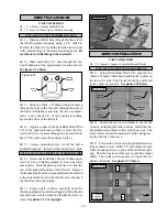
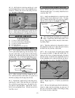
3) Remove the stabilizer. Using a modeling
knife, remove the covering from below the lines you
drew. Also remove the covering from the bottom edge
of the stabilizer, the bottom edge of the dorsal fin and
between the lines you drew on top of the fuselage.
See photo # 21 below.
Photo # 21
When cutting through the covering to remove
it, cut with only enough pressure to only cut
through the covering itself. Cutting into the balsa
structure may weaken it.
q
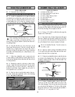
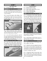
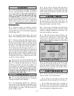
4) Slide the vertical stabilizer back in place.
Using a triangle, check to ensure that the vertical sta-
bilizer is aligned 90º to the horizontal stabilizer. See
figure # 11 below.
Figure # 11
HINGING THE ELEVATOR HALVES
q
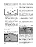
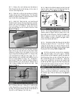
10) Hinge the two elevator halves using the same
technique as with the ailerons.
Be careful not to use too much C/A at one time
as the excess C/A may run down the length of
the hinge lines. Once cured, the elevator halves may
be stiff and difficult to move. This is normal. Gently
move them up and down about five to ten times to
free them up.
Remove
Covering
Draw
Line
Draw
Line
Remove
Covering
Draw
Line
90º
Vertical
Stabilizer
Horizontal
Stabilizer


