10
q
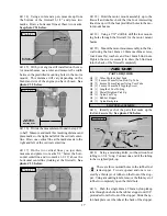
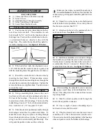
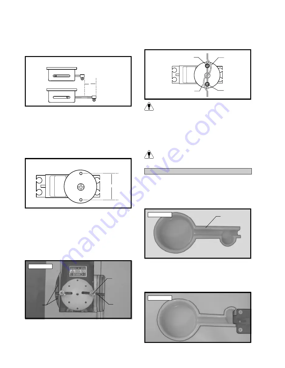
11) Using a ruler, measure the distance your re-
tract mechanism moves from the full up and locked
position to the full down and locked position. For
most retracts this measurement should be about 1”.
See figure # 5 below.
Figure # 5
q
12) To secure the two pushrod wires to the servo
wheel, we suggest using EZ Connectors. For the
mechanism to work properly the EZ Connectors need
to be installed on the servo wheel the exact distance
apart as the distance your retract mechanism travels.
You may need to drill your own holes through the
servo wheel if there are no predrilled holes that fit the
proper measurement. See figure # 6 below.
Figure # 6
q
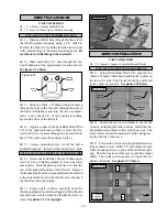
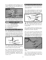
13) With the EZ Connectors installed on the
servo wheel slide the threaded wires through the con-
nectors. With the gear in the full UP and locked posi-
tion, attach the servo wheel to the servo so that the
EZ Connectors and wires are opposite each other. If
necessary, use a modeling knife and remove a por-
tion of the top sheeting to allow clearance for the servo
wheel and connector. See photo # 13 below.
Photo # 13
q
14) Double check that the retracts are in the full
up and locked position. Tighten the set screws in the
EZ Connectors and cut off the excess wires, leaving
5/16” beyond each EZ Connector as shown above.
q
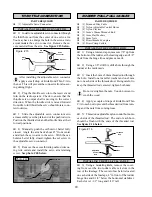
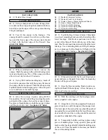
15) Rotate the servo wheel 180º so the retracts
are in the full down and locked position. Use pliers
and carefully bend each of the wires to prevent them
from hitting the EZ Connectors. See figure # 7 below.
Figure # 7
When you make the bend in the two wires, this
will shorten the wires slightly. You may need to
readjust the length of the wires using the EZ Connector.
q
16) Rotate the servo wheel back and forth to test
the operation of the retracts. If any binding is present
make small bends or adjustments in the linkage.
It is important that the retract linkage operates
smoothly. Any binding can cause the retract
servo to stall and result in excessive battery drain.
INSTALLING THE RETRACT GEAR COVERS
q
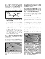
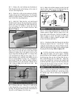
17) Using Lexan Canopy Scissors or a model-
ing knife, cut out both plastic retract gear covers, leav-
ing about a 1/8” lip around the entire perimeter to use
as a gluing surface. Cut the two gear covers apart in
the center. See photo # 14 below.
Photo # 14
q
18) Test fit the two gear covers in place on the
wing. They should fit inside the gear cutout and the
lip should rest flush on the wing surface. You may
have to make minor adjustments to fit your particular
retract installation. See photo # 15 below.
Photo # 15
X
X = Distance of
Actuator Arm
Travel
X
X = Measurement From Step # 11
EZ
Connector
Pushrod
Wire
Remove
Sheeting
Make
Bend
Make
Bend
EZ
Connector
EZ
Connector
1/8” Lip for
Gluing Surface


