


14
MOUNTING THE VERTICAL STABILIZER
q
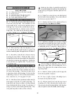
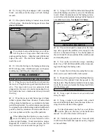
5) When you are sure that everything is aligned
correctly, mix up a generous amount of Kwik Bond
30 Minute Epoxy. Apply a thin layer to the mount-
ing slot in the top of the fuselage and to the sides
and bottom of the vertical stabilizer mounting area.
Apply epoxy to the bottom edge of the dorsal fin
and to the top of the fuselage also. Set the stabilizer
in place and realign. Double check all of your mea-
surements once more before the epoxy cures. Hold
the stabilizer in place with T-pins or masking tape
and remove any excess epoxy using a paper towel
and rubbing alcohol. Allow the epoxy to fully cure
before proceeding.
HINGING THE RUDDER
q
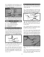
6) Hinge the rudder using the same technique
as with the ailerons and elevator halves.
Be careful not to use too much C/A at one time
as the excess C/A may run down the length of
the hinge line. Once cured, the rudder may be stiff
and difficult to move. This is normal. Gently move
it back and forth about five to ten times to free it up.
PARTS REQUIRED
q
{1} Nylon Tail Wheel Bracket
q
{1} Nylon Tail Wheel Tiller Arm
q
{1} Prebent Tail Wheel Wire
q
{1} 25mm Diameter Tail Wheel
q
{1} 2mm x 40mm Wire Pin
q
{2} 2mm Wheel Collars
q
{2} Brass Bearing Inserts
q
{2} 2mm x 5mm Machine Screws
q
{3} 3mm x 10mm Wood Screws
TAIL WHEEL INSTALLATION
TAIL WHEEL BRACKET ASSEMBLY
q
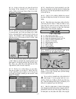
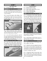
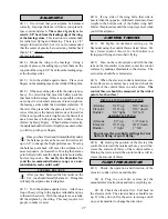
1) Slide one brass bearing, flange side down,
onto the tail wheel wire. Insert the wire up through
the bottom of the tail wheel bracket. Slide the second
brass bearing, flange side up, onto the wire. Push
firmly on each bearing to seat them into the top and
bottom of the bracket. See figure # 12 below.
Figure # 12
q
2) Insert one 2mm wheel collar into the molded
recess in the tail wheel tiller arm. Align the hole in
the wheel collar with the hole in the side of the tiller
arm. Install the 2mm x 5mm machine screw.
q
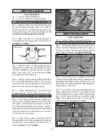
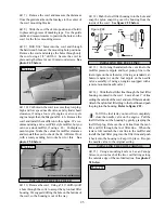
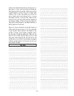
3) Slide the tail wheel tiller arm onto the tail
wheel wire. The arm should be positioned straight
back from the bracket and 90º to the axle The coil in
the wire should face forward. Tighten the machine
screw to secure the assembly in place. See photo #
22 below.
Photo # 22
q
4) Set the tail wheel assembly in place. The
pivot point of the tiller arm should be even with the
rudder hinge line and the tail wheel bracket should be
centered on the bottom of the fuselage.
q
5) Using a pen, mark the locations of the three
mounting screws. Remove the tail wheel bracket and
drill 5/64” pilot holes at the locations marked.
q
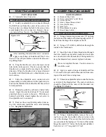
6) Secure the tail wheel bracket in place using
three 3mm x 10mm wood screws. Be careful not to
overtighten the screws. See photo # 23 below.
MOUNTING THE TAIL WHEEL ASSEMBLY
Photo # 23
q
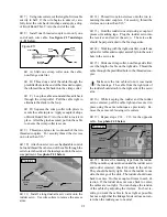
7) Using a ruler and a pen, measure back and
place a mark on the bottom edge of the rudder 1-1/4”
back from the rudder's leading edge.
q
8) Rotate the tiller arm to the side. Using a 5/64”
drill bit, drill a hole into the bottom of the rudder at
the mark made. Drill the hole at least 3/4” deep and
parallel with the rudder hinge line.
Tail Wheel
Bracket
Brass
Bearing
Brass
Bearing
Tail Wheel
Bracket
Tiller
Arm
Tail Wheel
Wire
Set
Screw
Tiller
Arm
Tail Wheel
Bracket


