Appendix B
www.glentek.com
18
MANUAL # 9675-1035-000-A
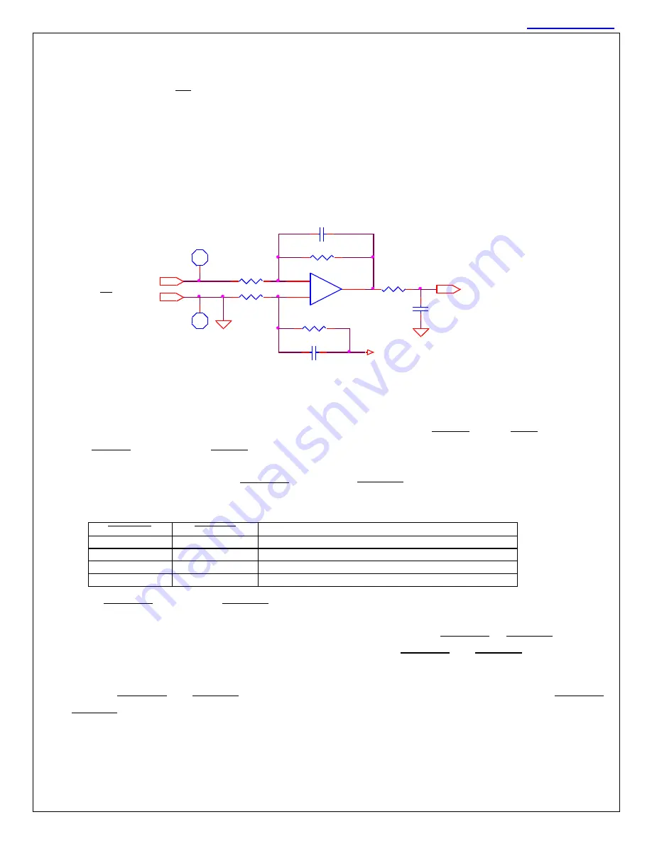
B-3 Analog Input, Command Signal
Pins
SPINDLE CMD
and
F T/SPEED COM
are the command input pins. The command input takes a differential
analog signal as referenced to the spindle drive
’s ground. Input voltage is expected to range from -10 volts
to +10 volts (typical).
The velocity command signal will be 0 to +10 VDC in unipolar control (non-rigid tap mode), ±10 VDC for
bipolar control (rigid tap mode).
Note
: CMD COMMON (AGND) is connected to Logic Common (Digital GND) inside the spindle drive.
B-4 Controller Inputs/Outputs - Direction Control,
WYE /
,
HIGH/
GAIN
Inputs,
Input, and
Output
The spindle drive accepts
SPINDLE
F RW R
and
SPINDLE
REVERSE
signals for operating four rotation
commands.
ACTION
closed
open
drive on, CCW rotation, unipolar speed control
open
closed
drive on, CW rotation, unipolar speed control
closed
closed
drive on, bipolar speed and direction control
open
open
drive off, no voltage or flux to the motor
SPINDLE
F RW R
and
SPINDLE
REVERSE
are enable and direction control signals. That is, each signal
enables motor movement in one direction. If both signals are closed (the signals are pulled low), motor
movement in both directions is enabled. When only one enable is closed (
F RW R
or
REVERSE
on), the
velocity command is unipolar, and when both enables are closed (
F RW R
and
REVERSE
on), the velocity
command is bipolar.
When both
F RW R
and
REVERSE
are closed, the spindle drive is in rigid tap mode. When only
F RW R
or
REVERSE
is closed, the spindle drive is in non-rigid tap mode (sometimes calle
d “inverter” mode). Both
rigid tap mode and non-
rigid tap (“inverter”) mode are used with vector drives. Inverters or VF drives use
non-rigid tap mode only.
332
SPEED CMD
0.33uF
10.0K
-
+
TLE084
10
9
8
TP6
AGND
0.022uF
Vref
0.022uF
AGND
FLT/SPEED COM
TP5
1.50K
1.50K
TO DSP A/D CONVERTER
10.0K
Command Signal Analog Input Schematic


