gledhill SysteMate 125 Installation And Servicing Instructions Download Page 32

Supplied By www.heating spares.co  Tel. 0161 620 6677

Page 32

Page 33

SY

STEMA

TE 

2000

3. Causes of ‘Unsatisfactory Space Heating’

Check the boiler thermostat - this should be 
set at maximum.
Check that the boiler flow temperature before 
it  is  switched  off  is  adequate  -  it  should  not 
be less than 80°C.
Check  the  operation  and  the  settings  of 
the  heating  programmer  and  the  room 
thermostat.
Check  that  the  heating  system  pump  is 
circulating the water to the radiator circuit.
If some rooms are not being heated properly, 
then  balance  the  system,  adjust  the  pump 
speed  and  check  the  operation  of  the 
thermostatic radiator valves (if fitted).

Overflow from Feed and Expansion Cistern

Check that the controlled level of water in the 
cistern  is  no  higher  than  necessary.    Adjust 
if required.

3.4 FAULT FINDING

Despite everyone’s best efforts some problems could occur and lead to complaints 
from the householder.

Complaints can be grouped into the following three main categories:-

1.  The system is noisy
2.  Hot water service is unsatisfactory
3.  Space heating is unsatisfactory

The  following  checks  should  be  carried  out  by  the  installer  before  calling  the 
manufacturer.

1.  Causes of a ‘Noisy’ System

Noisy pump operation
Check the level of water in the Appliance F & E cistern - adjust and vent the plate 
heat exchanger pump and system if necessary.
Check  and  if  necessary  adjust  the  pressure  in  the  heating/primary  system  and 
vent the system.
Check the pump speed setting of the boiler pump - reduce if necessary but ensure 
that the temperature rise across the boiler does not exceed 11°C.
Check the pump speed setting of the heating pump - reduce if necessary but ensure 
a temperature difference across the flow and return does not exceed 11°C.
Check and adjust if necessary the heating system bypass valve.
Check that the radiators are correctly balanced.

Noisy boiler operation
Check the flow rate through the boiler at full gas rate by measuring the temperature 
rise  across  the  boiler.    If  the  temperature  rise  is  greater  than  11°C,  then  increase 
the pump speed. 
Check 
 and adjust if necessary the pressure in the heating/primary system.
Check and vent the system if necessary.

Noise when hot water tap is opened
If  the  plate  heat  exchanger  pump  is  noisy  when  the  hot  water  tap  is  opened, 
then  check  the  level  of  water  in  the  appliance  F  &  E  cistern  and  vent  the  pump 
if necessary.
Water hammer - loose pipework and/or tap washers.

2. Causes of ‘Unsatisfactory Hot Water Service’

Check that the SysteMate is full of water i.e. level of water in the appliance F & E 
cistern is correct when system is cold.
Check boiler thermostat - this should be set at maximum.
Check  that  the  boiler  flow  temperature  is  adequate  when  it  stops  firing.    Boilers 
should provide a flow temperature of 82 ± 3°C but temperatures as low as 76°C will 
allow the SysteMate 2000 to provide a satisfactory performance.
Check that the store is charging to at least 73°C.
Check that the hot water plate heat exchanger pump starts when the hot water tap 
is opened and stops shortly after it is closed.
Check that the plate heat exchanger pump is set at maximum speed.
Check that the space heating and hot water load is not greater than the boiler output 
and that the SysteMate 2000 model is suitable for the type of dwelling.
If all the above checks are satisfactory then it is possible that the performance of 
the heat exchanger is impaired by scale.  In this case the hot water flow rate will be 
noticeably less than the cold water flow rate.  Replace with a factory exchange unit 
and re-check hot water performance.

3.0 SERVICING

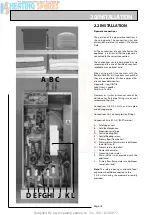
The  ACB  can  be  used  to  establish/check 
the  operating  and  set  temperatures  of  the 
appliance  as  well  as  identify  faults  on  any 
of  the  3  sensors.   This  is  done  by  operating 
switches SW1 and SW2 as shown opposite and 
reading the LED display.  (See page 27)

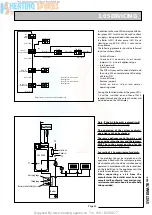
Store T1,  PHE T2,  and  DHW T3  indicate  the 
current  value  being  read  by  the  store,  PHE 
and  DHW  sensors  respectively. The  location 
of the sensors is shown in the diagram shown 
opposite/below.

T1 ON and T1 OFF show the store temperature 
set  points  which  are  automatically  reset  on 
each  boiler  cycle  to  match the temperature 
produced by the boiler.

T1  ON  shows  the  temperature  at  which  the 
store will call for heat, i.e signal the boiler to fire.
T1  OFF  shows  the  temperature  at  which  the 
store  will  be  satisfied,  i.e  signal  the  boiler  to 
switch off.

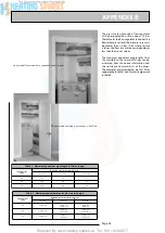
POWERFLUSHING/CLEANING  OF  THE 
HEATING SYSTEM

If  it  is  proposed  to ‘powerflush’  the  heating 
system  we  would  recommend  that  the 
SysteMate  appliance  is  isolated  from  the 
heating system being cleaned.  Failure to do 
this could seriously damage the appliance.

When  carrying  out  the  work  always  comply 
fully  with  the  manufacturers  instructions  for 
the powerflushing equipment being used.  

If  in  any  doubt  please  consult  our Technical 
Helpline.

Summary of Contents for SysteMate 125

Page 1: ... SEALED CENTRAL HEATING AND MAINS PRESSURE HOT WATER SUPPLY SYSTEM INCORPORATING A THERMAL STORE ALL MODELS COMPLY WITH THE WATER HEATER MANUFACTURERS SPECIFICATION FOR HOT WATER ONLY THERMAL STORES SYSTEMATE 2000 SYSTEMATE 2000 Gas Council Approved Reference Numbers SysteMate 125 97 317 26 SysteMate 145 97 317 27 SysteMate 185 97 317 28 SysteMate 210 97 317 29 SysteMate 225 97 317 30 ...

Page 2: ...roduct is manufactured under a BS EN ISO 9002 Quality System audited by BSI Patents Pending TheGledhillGroup sfirstpriorityistogivea high quality service to our customers Quality is built into every Gledhill product and we hope you get satisfactory service from Gledhill If not please let us know As part of the industry wide Benchmark Initiative all Gledhill SysteMates now include a Benchmark Insta...

Page 3: ...y i e central heating system The SysteMate 2000 is not covered by section G3 of the current Building Regulations and is therefore not notifiable to Building Control The information in this manual is provided to assist generally in the selection of equipment The responsibility for the selection and specification of the equipment must however remain that of the customer and any Designers or Consulta...

Page 4: ...t temperature of the domestic hot water is maintained by a printed circuit board which controls the speed of the pump circulating the primary water from the store through the plate heat exchanger Because of the innovative method of hot water production no in line scale reducer is normally required on the cold supply to the appliance If scale should become a problem the plate heat exchanger is easi...

Page 5: ...o t p u e z i s r e l i o b x a M k 5 1 W k 0 2 W k 5 2 W k 0 3 W k 5 3 W h c t i w S W k 9 W k 9 W k 9 W k 9 W k 9 s e p y t g n i l l e w D l a c i p y T s m o o r d e B 3 1 3 2 4 2 5 3 6 4 s m o o r h t a B 1 1 2 1 2 2 3 4 r e w o h s e t i u s n E 1 2 1 4 2 4 2 0 1 2 TECHNICAL DATA Notes 1 The SysteMate 225 appliance is suitable for use in large properties because it produces the same peak hou...

Page 6: ...mplete with cold feed open vent pipework assembly is supplied separately Optional Extra Equipment A soft water model is available for areas where the hardness level is below 200 p p m mg ltr Flexible connection kit for use in connection with suitable push fit connectors for quick connection to first fix pipe installation Switch emergency electrical back up for hot water and or heating in the event...

Page 7: ...C 5 2 1 M S m m 0 4 1 1 m m 5 9 5 m m 5 9 5 5 4 1 M S m m 0 4 1 1 m m 5 9 5 m m 5 9 5 5 8 1 M S m m 0 5 3 1 m m 5 9 5 m m 5 9 5 0 1 2 M S m m 5 9 4 1 m m 5 9 5 m m 5 9 5 5 2 2 M S m m 0 7 6 1 m m 5 9 5 m m 5 9 5 S N O I S N E M I D D R A O B P U C M U M I N I M l e d o M t h g i e H h t d i W h t p e D F D E 5 2 1 M S m m 0 9 8 1 m m 0 0 7 m m 0 0 6 5 4 1 M S m m 0 9 8 1 m m 0 0 7 m m 0 0 6 5 8 1 ...

Page 8: ...Supplied By www heating spares co Tel 0161 620 6677 Page 8 1 0 DESIGN 1 2 TECHNICAL DATA ...

Page 9: ...ied By www heating spares co Tel 0161 620 6677 Page 9 SYSTEMATE 2000 1 2 TECHNICAL DATA PERFORMANCE GRAPHS OF GRUNDFOS PUMPS 1 0 DESIGN GRUNDFOS 15 50 GRUNDFOS 15 60 litres sec 6 litres sec Note 1mW G 10kPa ...

Page 10: ...he cold inlet should be removed No check valve or similar device should be fitted on the cold water supply branch to the SysteMate 2000 Because of the innovative method of hot water production no scale reducer is required on the branch to the appliance However to comply with the Benchmark Guidance Note for Water Treatment in Heating and Hot Water Systems the installer should check the hardness lev...

Page 11: ...at plastic pipework systems can be used in place of copper internally as long as the chosen system is recommended for use on domestic hot and cold water systems by the manufacturer and is installed fully in accordance with their recommendations This is particularly important in relation to use of push fit connections when using the optional flexible hose kits see 2 2 Installation Pipework connecti...

Page 12: ...be used for sizing the heating circuit pipework 1 3 SYSTEM DETAILS For example At 24 litres min primary flow rate the pressure loss through the SysteMate 2000 model SM210 coil and fittings is 2 1m W G 21kPa The maximum pump head available at 24 litres min and setting 3 is 3 2m H2 O 32kPa therefore 1 1m W G 11kPa is available for the boiler circuit With sealed heating systems air is released during...

Page 13: ... systems in this manual are generally based on the use of BS EN Standard copper pipework and fittings However we are happy that plastic pipework systems can be used in place of copper internally as long as the chosen system is recommended for use on domestic heating systems by the manufacturer and is installed fully in accordance with their recommendations We always recommend the use of barrier pi...

Page 14: ...uired at the lockshield valves on the radiators If this is not done the performance of the SysteMate will be adversely affected Heating System Connection of Bathroom Radiator Towel Rail for Summer use 1 0 DESIGN 1 3 SYSTEM DETAILS Boiler sited above the SysteMate or with dipped flow and return pipes A gravity check valve should be fitted in the boiler return pipework to prevent gravity circulation...

Page 15: ...reased load Full details of the requirements are provided in Section 2 1 Site Requirements and 2 2 Installation Otherwise the design requirements are the same as the standard appliance Switch can operate on hot water or hot water and heating modes In the former only hot water pump and electric heating element are energized In the latter the heating system pump is also energized This means that the...

Page 16: ...ble location will be needed for the separate feed and expansion cistern and expansion vessel This will often be at high level in the cupboard housing the SysteMate2000 Thedimensions and clearances are provided in section 1 2Technical Data The location will need to provide a suitable route for the cold feed expansion pipe and the open safety vent pipe for the appliance as well as the connecting pip...

Page 17: ... should be handled carefully to avoid damage and the recommended method is shown opposite Before installation the site requirements should be checked and confirmed as acceptable The plastic cover and protective wrapping should be removed from the appliance and the installation base provided placed in position The appliance can then be lifted into position in the cupboard on top of the base and the...

Page 18: ... Speedfit Yorkshire Tectite However as similar assurances cannot be obtained for Polypipe fittings we cannot recommend their use Connections A B D E F G H I and L are plain ended copper pipe Connections C J are compression fittings Connection K is a RC1 2 1 2 BSPT internal A Safety open vent B Cold feed expansion C Expansion vessel pipe D Central heating flow E Central heating return F Primary flo...

Page 19: ...lation in case they have been loosened during transit The fittings for the feed and expansion cistern should be installed following the instructions provided by the manufacturer in a position to suit the particular location and the cistern fitted on its supports base The cold feed expansion and safety open vent should be installed between the appliance and the feed and expansion cistern Combined f...

Page 20: ...plied By www heating spares co Tel 0161 620 6677 Page 20 WIRING DIAGRAM STANDARD SYSTEMATE 2000 APPLIANCE 2 0 INSTALLATION 2 2 INSTALLATION Y E K L B E U L B R B N W O R B Y G W O L L E Y N E E R G R D E R ...

Page 21: ... wiring panel ElectricalConnection StandardAppliance The SysteMate 2000 is pre wired to a 12 way terminal strip from the A C B and plumbers are well able to complete the electrical installation provided they adhere strictly to the IEE Requirements for Electrical Installations BS 7671 A schematic arrangement of the wiring is shown on page 24 All the terminals are suitably labelled Note Do not attem...

Page 22: ...ome loose during transit Frost Protection When frost protection is required for the whole house or where a base temperature is required during cold weather then a frost thermostat should be wired across plug in terminals 21 and 23 on the A C B board An alternative to fitting a frost thermostat would be to set the programmer to constant during the time required and adjust the room thermostat to a s...

Page 23: ...s co Tel 0161 620 6677 Page 23 SYSTEMATE 2000 2 0 INSTALLATION 2 2 INSTALLATION WIRING DIAGRAM SYSTEMATE2000 WITH SWITCH Y E K L B E U L B R B N W O R B Y G W O L L E Y N E E R G R D E R K L B K C A L B Y W O L L E Y H W E T I H W ...

Page 24: ... cable provided through the service slot provided in the base of appliance and connect to the isolator as follows red live black neutral green yellow earth Check the cables are secure in the grips provided below the terminal strip and ensure they are not in contact with any hot surfaces The recommendations contained under Electrical Connection Standard Appliance should be followed when connecting ...

Page 25: ...ails of the requirements are given in PAS 33 1999 under Section 10 Commissioning When using either cleansing or corrosion inhibitor chemical the manufacturers instructions must be followed Cleansing the Primary System It is very important to ensure that the Primary system is cleaned using a suitable cleansing agent such as Sentinel X300 or Fernox Superfloc to ensure that any flux residues installa...

Page 26: ...on the A C B shown opposite 1 Set the boiler thermostat to MAXIMUM 2 Switch off heating on the clock programmer and room thermostat 3 Check the jumper settings are correct Thesemustallbeinthecorrectpositions for the appliance to work correctly see opposite for options 4 Switch on the mains supply The A C B will automatically commission itself to suit the sytem boiler and the dot after the ON the L...

Page 27: ...d to be allowed for this to happen during initial commissioning This will vary depending on the boiler size and the model of the SysteMate 2000 being used 2 Once a temperature of 64 C has been reached on the thermal store switch on space heating clock programmer and room thermostat Horizontal LED bar 1 HT will light Green LED 3 on the A C B will switch on Heating pump will run 3 Switch off space h...

Page 28: ...ust the ballvalve so that the water level in the appliance F E cistern when the system is cold is correct and does not overflow when the appliance is at maximum temperature DO turn down the servicing valve for the ballvalve in the F E cistern once the system is finally filled to the point where the warning overflow pipe will cope with the discharge arising from a ballvalve failure DO make sure tha...

Page 29: ...obtained direct from Gledhill using the Speed Spares service or throughanyofthelargerplumbersmerchants specialist heating spares suppliers Help and advice is also available from the Technical Helpline on 01253 474401 However allcomponentsarereadilyaccessible and can be changed quickly and easily by the installer using common plumbing practice If it is necessary to replace any of the pumps fitted t...

Page 30: ... C A d r a o b l o r t n o c e c n a i l p p A k o l E 5 5 2 B X 8 5 1 9 3 E 1 1 r o s n e s e r o t S k o l E 9 4 1 T G 2 2 0 6 2 E 2 1 r o s n e s n r u t e r E H P k o l E 3 5 1 T G 4 2 0 6 2 E 3 1 r o s n e s e r u t a r e p m e t W H D k o l E 3 5 1 T G 4 2 0 6 2 E 4 1 k c o l c l a c i n a h c e m o r t c e l E n i l s s a r G 5 1 2 B X 3 7 8 5 8 3 5 1 k c o l c l a t i g i D n i l s s a r G...

Page 31: ...Supplied By www heating spares co Tel 0161 620 6677 Page 31 SYSTEMATE 2000 3 0 SERVICING ...

Page 32: ...he appliance F E cistern and vent the pump if necessary Water hammer loose pipework and or tap washers 2 Causes of Unsatisfactory Hot Water Service Check that the SysteMate is full of water i e level of water in the appliance F E cistern is correct when system is cold Check boiler thermostat this should be set at maximum Check that the boiler flow temperature is adequate when it stops firing Boile...

Page 33: ... visit from the manufacturer the installer must have the completed Benchmark commissioning service record sheet to hand to enable help to be provided InadditiontothemainLEDdisplaytheACBhas four green LED S which can be used to check a supply is being provided when required to the Boiler LED 1 Boiler pump LED 2 and Heating pump LED 3 LED 4 is not used on this appliance The following procedure shoul...

Page 34: ...ing Range In Line regulators as in Option 4 for Taps Mixers APPENDIX A WATER SAVINGS OPTIONS FOR SHOWERS 4 FIXING OPTIONS FOR TAPS MIXERS 1 MK Range Combined Regulators Aerator for screwing onto Taps Mixers with internal or external threads on their noses AntiVandal models also available 2 MR05 T Range Internal Regulators Push fit into Tap or Mixer seats Produced in three sizes 12 5mm BS1010 12mm ...

Page 35: ...d in another cupboard close to the appliance if required 0 5 0 P I M e d o C k c o t S 1 e p y t d l o f i n a M m o o r k a o l c e n o m o o r r e w o h s e t i u s n e e n o m o o r h t a b e n o r o t a l u g e r w o l F e t u n i m s e r t i l g n i t t i f l a n i m r e T s t e l t u o d l o f i n a m r e t a w t o H y t i t n a u Q s t e l t u o d l o f i n a m r e t a w d l o C y t i t n a...

Page 36: ... for plastic pipework in table 2 r e p p o c m m 5 1 n i h t g n e l e p i p t n e l a v i u q e m u m i x a M 1 e l b a T e r u s s e r p t e l n I r a b m e p i p f o h t n e l t n e l a v i u q e m u m i x a M m l 8 m l 0 1 m l 8 1 0 2 3 3 3 1 5 5 2 0 1 1 5 4 7 1 0 3 0 0 2 0 8 0 3 e p i p c i t s a l p n i s h t g n e l e p i p t n e l a v i u q e m u m i x a M 2 e l b a T e r u s s e r p t e l...

Page 37: ...ved and the actual connection of fittings to the manifold will need to suit the arrangements shown in page 35 Note 1 If it is proposed to fit chemical water treatment such as a water softener this should be fitted in this location and the cold water branch in the sink should be branched off the cold water main prior to the treatment device instead of the cold water manifold Any other isolating con...

Page 38: ... AND FURTHER we will meet the contractors installers reasonable costs in removing and replacing any defective Open Vented Copper Cylinder or Tank with defective integral pipework as follows Gledhill Water Storage Ltd AMD AUGUST 2000 Where we agree to rectify any defect we reserve the right to undertake the work on our own premises Provided that our product has been installed in accordance with any...

Page 39: ... to enter at any time any vehicle or premises owned or occupied by the Purchaser or in the possession of the Purchaser for the purposes of repossessing and recovering any such goods the property in which has remained in us under paragraph 2 above We shall not be responsible for and the Purchaser will indemnify us against liability in respect of damage caused to any vehicle or premises in such repo...

Page 40: ...Supplied By www heating spares co Tel 0161 620 6677 Page 40 ...

Page 41: ...Supplied By www heating spares co Tel 0161 620 6677 ...

Page 42: ...Supplied By www heating spares co Tel 0161 620 6677 ...

Page 43: ...Supplied By www heating spares co Tel 0161 620 6677 ...

Page 44: ...Supplied By www heating spares co Tel 0161 620 6677 ...

Reviews: