


Supplied By www.heating spares.co Tel. 0161 620 6677
Page 16
Page 17
SY
STEMA
TE
2000
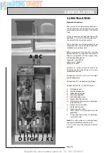
2.0 INSTALLATION
2.1 SITE REQUIREMENTS
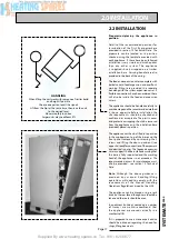
The appliance is designed to be installed in an airing/cylinder cupboard and the
relevant minimum dimensions are provided in section 1.2 Technical Data.
Because of the ease of installation we recommend that the cupboard construction
is completed and painted before installation of the appliance. The cupboard door
can be fitted after installation.
If the unit needs to be stored prior to installation it should be stored upright in a dry
environment and on a level base/floor.
Installation and maintenance access is needed to the front of the appliance and
above the F & E cistern. See Technical Data section for further details.
The minimum dimensions contained in section 1.2 Technical Data allow for the
passage/connection of pipes to the appliance from any direction as long as the
appliance is installed on the installation base provided. If the installation base is
not used extra space may be needed to allow connection to the pipework and the
whole of the base area should be continuously supported on a material which will
not easily deteriorate if exposed to moisture.
The floor of the cupboard needs to be level and even and capable of supporting
the weight of the appliance when full. Details of the weight when full is provided
in section 1.2 Technical Data.
The appliance is designed to operate as quietly as practicable. However, some noise
(from pumps etc) is inevitable in any heating system. This will be most noticeable
in cupboards formed on bulkheads, or at the mid span of a suspended floor. In these
cases the situation can be improved by placing the appliance on a suitable sound
deadening material (i.e. carpet underlay or similar).
Cupboard temperatures will normally be higher than in a conventional system and
the design of the cupboard and door will need to take this into account. No ventilation
is normally required to the cupboard.
A suitable location will be needed for the separate feed and expansion cistern
and expansion vessel. This will often be at high level in the cupboard housing the
SysteMate 2000. The dimensions and clearances are provided in section 1.2 Technical
Data. The location will need to provide a suitable route for the cold feed/expansion
pipe and the open safety vent pipe for the appliance as well as the connecting pipe
to the system expansion vessel. The location will also need to provide a suitable
route and discharge position for the warning/overflow pipe and the ballvalve supply
from the mains cold water system if these are being fitted.
Note: The standard appliance is supplied with a cistern without a ballvalve/
overflow for filling manually.
An electrical supply must be available which is correctly earthed, polarized and in
accordance with the latest edition of the IEE requirements for electrical Installations
BS 7671.
The electrical mains supply needs to be 230V/50Hz/1Ph
Connection must be made using a double-pole linked isolator with a contact
separation of 3mm in both poles which is located within 1m of the appliance. The
supply must only serve the appliance.
The supply to the standard appliance shall be fused at 3 amp - nominal maximum full
load current for all SM models = 1.4 amps (this does not include the boiler).
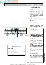
Electrical Supply requirements for
SysteMate
2000
with Switch
If the ‘Switch’ electrical emergency backup
is being provided, the minimum breaking
capacity of the main isolation switch and
cable sizes/lengths at 230V shall follow the
recommendations in the table below.
l
a
n
i
m
o
N
d
a
o
l
ll
u
f
t
n
e
r
r
u
c
f
o
g
n
i
t
a
r
n
i
M
g
n
i
t
a
l
o
s
i
h
c
t
i
w
s
e
z
i
s
e
l
b
a
C
d
e
d
n
e
m
m
o
c
e
r
.
x
a
M
n
o
d
e
s
a
b
-
n
u
r
e
l
b
a
c
4
.
0
d
n
a
p
o
r
d
V
2
.
9
n
o
i
t
c
e
n
n
o
c
s
i
d
d
n
o
c
e
s
e
p
y
t
a
g
n
i
s
u
e
m
i
t
r
e
k
a
e
r
b
B
r
o
1
s
p
m
A
0
.
1
4
s
p
m
A
5
4
m
m
0
1
2
s
e
r
t
e
m
9
4
t
i
u
c
r
i
c
d
e
d
n
e
m
m
o
c
e
R
d
e
s
a
b
-
e
c
i
v
e
d
n
o
i
t
c
e
t
o
r
p
n
o
i
t
c
e
n
n
o
c
s
i
d
d
n
o
c
e
s
4
.
0
n
o
e
m
i
t
1
7
8
3
S
B
o
t
.
B
.
C
.
M
-
1
e
p
y
t
A
5
4
N
E
S
B
o
t
r
e
k
a
e
r
b
t
i
u
c
r
i
c
B
e
p
y
t
A
5
4
8
9
8
0
6
Summary of Contents for SysteMate 125
Page 8: ...Supplied By www heating spares co Tel 0161 620 6677 Page 8 1 0 DESIGN 1 2 TECHNICAL DATA ...
Page 31: ...Supplied By www heating spares co Tel 0161 620 6677 Page 31 SYSTEMATE 2000 3 0 SERVICING ...
Page 40: ...Supplied By www heating spares co Tel 0161 620 6677 Page 40 ...
Page 41: ...Supplied By www heating spares co Tel 0161 620 6677 ...
Page 42: ...Supplied By www heating spares co Tel 0161 620 6677 ...
Page 43: ...Supplied By www heating spares co Tel 0161 620 6677 ...
Page 44: ...Supplied By www heating spares co Tel 0161 620 6677 ...