Page 18
Page 19
INSTALLATION
INSTALLATION
INSTALLATION
INSTALLATION
Programmer
Fuse
Spur
L
N
E
L
N
On
On
Off
Off
HW
CH
Store
thermostat
E
C
1
2
2
port
zone
valve
ML MN E PL SL
Room
thermostat
E
C
1
2
3
port
divert
valve
ML MN E PL SL
Wiring
diagram
– no
pump
required
Programmer
Fuse
Spur
L
N
E
L
N
On
On
Off
Off
HW
CH
Store
thermostat
E
C
1
2
2
port
zone
valve
ML MN E PL SL
Room
thermostat
E
C
1
2
3
port
divert
valve
ML MN E PL SL
Wiring
diagram
– CH
pump
required
CH
Pump
L
N
E
Programmer
Fuse
Spur
L
N
E
L
N
On
On
Off
Off
HW
CH
Store
thermostat
E
C
1
2
2
port
zone
valve
ML MN E PL SL
Room
thermostat
E
C
1
2
3
port
divert
valve
ML MN E PL SL
Wiring
diagram
– HW
&
CH
pump
required
CH
Pump
L
N
E
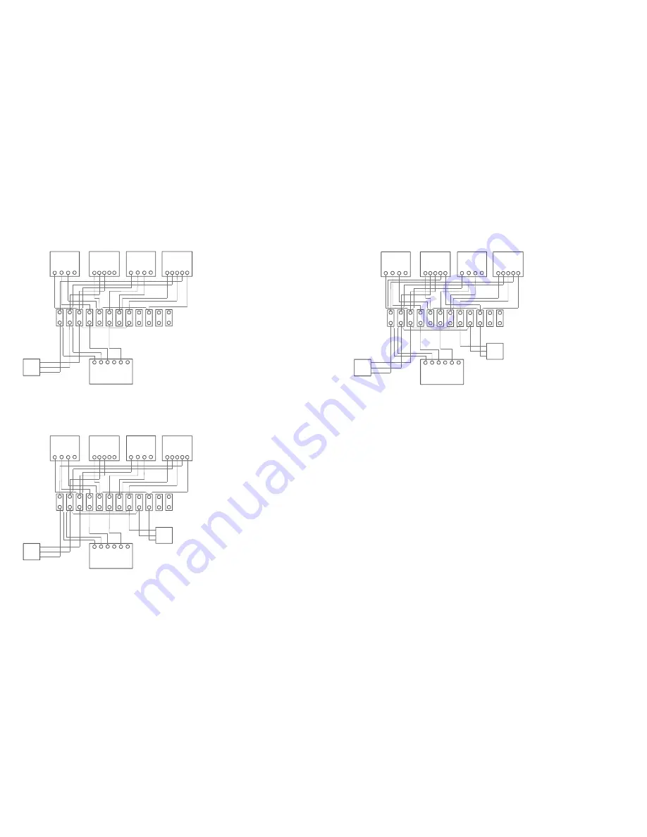
The following control wiring diagrams ensure
that the district heating system is isolated from
the dwelling when charging is not required.
Please note, it is part of the commissioning
process to ensure the controls are functioning
correctly.


