3
Come prima operazione pe il montaggio
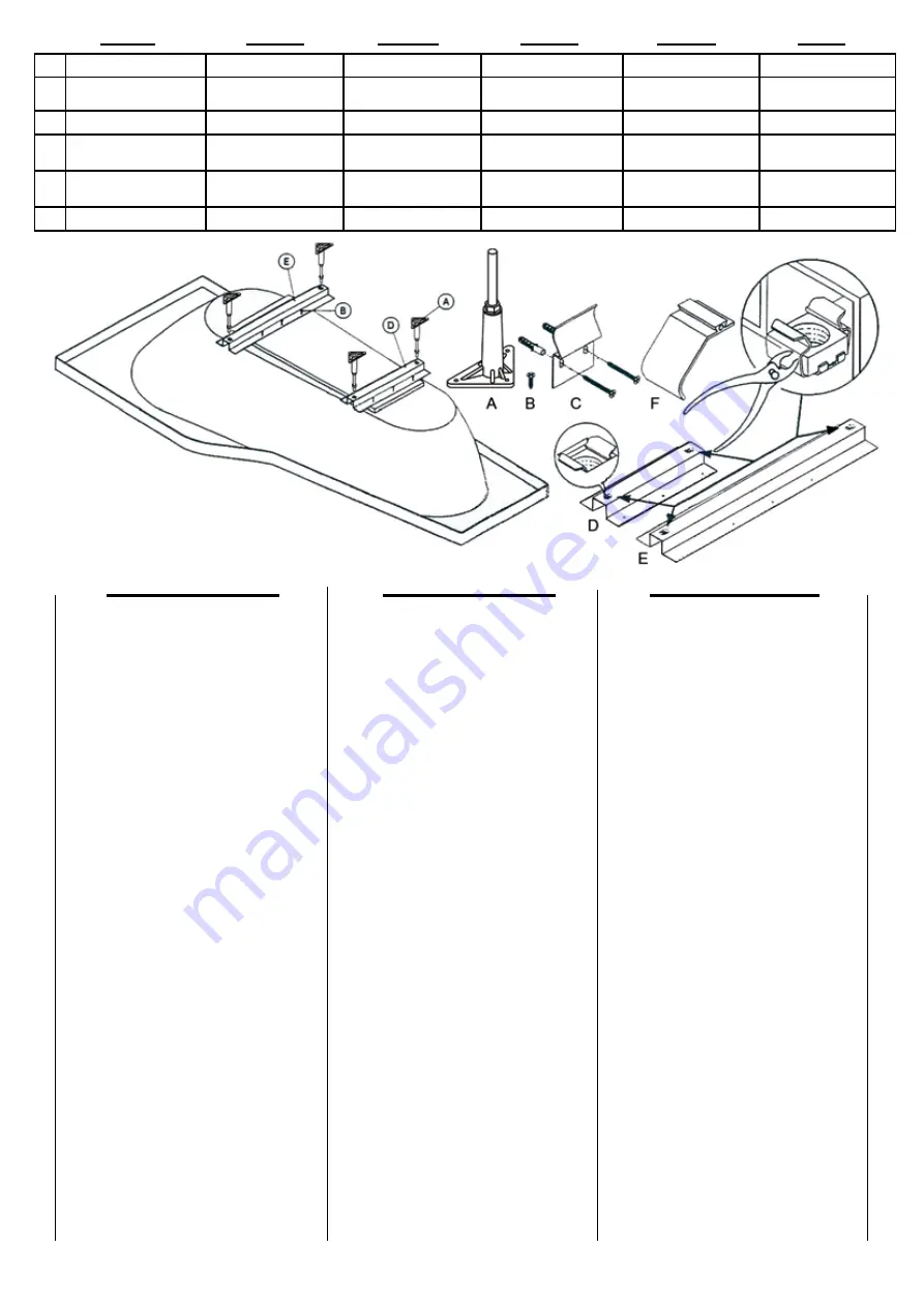
predisporre la vasca per l’inserimento dei piedini
di appoggio:
1. Capovolgere la vasca adagiandola sui fogli
dell’imballo per evitare di danneggiarla.
2. Fissare le staffe metalliche con guida a U
(part D - E Fig.3) alla tavola di rinforzo della
vasca utilizzando le 6+6 viti a testa svasata
piena (part B fig.3).
3. Avvitare i piedini di appoggio (part A Fig.3)
alle guide a U.
4. Montare la colonna di scarico ad altri
eventuali accessori sulla vasca.
5. Provvedere, agendo sui piedini di appoggio,
al livellamento del piano e alla sua
regolazione in altezza; nel caso in cui la
vasca venga montata con pannelli laterali,
la misura “K” (distanza tra il pavimento e
il bordo inferiore della vasca Fig.4) deve
essere compresa tra i 515 e 520 mm.
6.
Tracciare sulle pareti una linea in
corrispondenza del bordo della vasca.
7. Spostare la vasca.
8. Bloccare i piedini serrando i controdadi.
9. Calcolare la misura “H” (altezza misura
vasca Fig.6) e “G” (misura fissa di 15 mm
fig.6)
10.Praticare i fori per i supporti a parete (part.
C fig.5)
11.Fissare i supporti a parete.
12.Ricollocare la vasca nella posizione
definitiva.
13.Togliere l’eventuale pellicola protettiva che
avvolge la vasca .
14.Controllare che la vasca sia sostenuta
contemporaneamentesia dai piedini che
dai supporti a parete e che il suo peso sia
equamente ripartito.
15.Collegare il sifone dello scarico all’attacco
della colonna.
16.Riempire d’acqua e controllare eventuali
perdite.
17.Sigillare il contorno del bordo vasca con
silicone antimuffa dopo aver ben pulito le
superfici a contatto.
GB
D
I
A
Piedini di appoggio
Feet
Stützfüße verstellbare
Support pour pied
Piés de apoyo
Badpoten
B
Vita a testa svasata piena Flathead screws
Flache
Senkkopfschrauben
Vis a tête évasée
Tornilos con cabeza
avallanada plata
Schroeven
C
Supporti da parete
Wall support
Wandhalterungen
Fixations murales
Soportes para pared
Zlemmen
D
Staffa metallica piccola
con guida a U
Small metal bracket with
U-shaped guide
Fußplatte klein
Traverse metalique
avec guide a U (petite)
Grapa metálica pequeña
con guía a U
Kleine metalen klem
met U-vorm hulp
E
Staffa metallica grande
con guida a U
Large metal bracket with
U-shaped guide
Fußplatte groß
Traverse metalique
avec guide a U (grande)
Grapa metálica grande
con guía a U
Grote metalen klem
met U-vorm hulp
F
Molle
Springs
Federklammer
Ressorts en plastic
Resortes
Plastic schuifjes
D
GB
F
E
NL
I
The first assembly operation is to prepare the
bath for inserting the feet:
1. Turn the bath upside down, resting it on
pieces of packaging to avoid damage.
2. Fix the metal brackets with U-shaped guide
(Part. D and E fig.3) to the bath reinforcement
board using the 6+6 flathead screws (Part.B
fig.3).
3.
Screw the feet (Part. A fig.3) onto the
U-shaped guide
4. Fit the drain connection and any other fitting
onto the bath.
5. Make sure the bath in level, adjusting the
height by means of the feet; if side or front
panels are to be assembled on the bath, the
measurement “K” (distance from the floor
to the bottom of the bath rim fig.4) must be
between 515 and 520 mm.
6. Draw a line along the walls at the level of the
bath edge.
7. Move the bath away.
8. Lock the feet in position by tightening the
lock nuts.
9. Calculate the measurement “H” (bath rim
height fig.6) and “G” (fixed measurement of
15 mm fig.6).
10.Drill holes for the wall support (Part. C fig.5)
at about 100 mm from the corners.
11.Fix the wall supports.
12.Put the bath back in its final position.
13.Remove any protective film from the bath.
14.Check that the bath is equally supported by
and its weight distributed between the feet
and the wall supports.
15.Connect the trap to the drain connection.
16.Fill with water and check for leaks.
17.Thoroughly clean the surface in contact
with the bath edge and seal with mould-
resistant silicone.
Für die Montage ist die Wanne als erstes für den
Einsatz der Stützfüße vorzubereiten:
1. Die Wanne umdrehen, wobei sie vorsichtig
auf Verpackungspapier aufzustzen ist, um
sie beschädigen.
2. Die Fußplatte (Teil D und E Abb.3)
an der Verstärkungsplatte der Wanne
unter Verwendung der 6+6 flachen
Sendkopfschrauben (teil B abb.3)
befestigen.
3. Die Stützfüße (teil A abb.3) in die U-förmigen
Führungen einschrauben.
4. Überlauf und Ablaufsyphon montieren (nicht
im Lieferumfang).
5.
Die Wanne durch Betätigung der
höhenverstellbanen Stützfüße waagerecht
ausrichten und die Höhe regulieren; falls
die Wanne mit Seiten- bzw. Frontblenden
versehen wird, muß das Maß “K” (Abstand
zwischen Boden und unterem Beckenrand
abb.4) zwischen 515 und 520 mm betragen.
6. Auf den Wänden eine Linie entsprechend
dem Beckenrand ziehen.
7. Die Wanne an die gewünschte Position
stellen und nochmals entsprechend der
markierten Linie ausrichten.
8. Die Füße durch Festziehen der
Gegenmuttern blockieren.
9. Das Maß “H” (Höhe des Beckenrandes
abb.6) und “G” (festes Maß von 15 mm
abb.6) addieren.
10.Die Bohrungen für die Wandhalterungen
(Teil C abb. 5) in einem Abstand von ca.
100mm von den Ecken ausführen.
11.Die Wandhalterungen befestigen.
12.Die Wanne wieder an der definitiven (s’.
oben) Position aufstellen.
13.Eventuell
vorhandene
Schutzfilme,
mit denen die Wannen versehen sind,
entfernen.
14.Überprüfen, daß die Wanne gleichzeitig
sowohl von den Füßen als auch von den
Wandhalterungen getragen wird, und daß
ihr Gewicht gleichmäßig verteilt ist.
15.Den Ablaufsyphon an die Abwasser-
Hausinstallation anschließen.
16.Die Wanne mit Wasser befüllen und auf
eventuelle Lecks überprüfen.
17.Die Kontaktflächen zwischen Wnad und
Wannenrand sorgfältig reinigen und mit
Antischimmelsilikon versiegeln.
fig. 3


