


- 59 -
BIOS Setup
BIOS (Basic Input and Output System) records hardware parameters of the system in the EFI on the
motherboard. Its major functions include conducting the Power-On Self-Test (POST) during system startup,
saving system parameters and loading operating system, etc. BIOS includes a BIOS Setup program that
allows the user to modify basic system configuration settings or to activate certain system features. When the
power is turned off, the battery on the motherboard supplies the necessary power to the CMOS to keep the
configuration values in the CMOS.
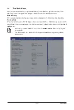
To access the BIOS Setup program, press the <DEL> key during the POST when the power is turned on.
Chapter 5 BIOS Setup
• BIOS flashing is potentially risky, if you do not encounter problems of using the current BIOS
version, it is recommended that you don't flash the BIOS. To flash the BIOS, do it with caution.
Inadequate BIOS flashing may result in system malfunction.
• It is recommended that you not alter the default settings (unless you need to) to prevent system
instability or other unexpected results. Inadequately altering the settings may result in system's
failure to boot. If this occurs, try to clear the CMOS values and reset the board to default values.
(Refer to the
Exit
section in this chapter or introductions of the battery/clearing CMOS jumper in
Chapter 4 for how to clear the CMOS values.)
BIOS Setup Program Function Keys
<
f
><
g
>
Move the selection bar to select the screen
<
h
><
i
>
Move the selection bar to select an item
<+>
Increase the numeric value or make changes
<->
Decrease the numeric value or make changes
<Enter>
Execute command or enter the submenu
<Esc>
Main Menu: Exit the BIOS Setup program
Submenus:
Exit
current
submenu
<F1>
Show descriptions of general help
<F3>
Restore the previous BIOS settings for the current submenus
<F9>
Load the Optimized BIOS default settings for the current submenus
<F10>
Save all the changes and exit the BIOS Setup program
Summary of Contents for G292-Z44
Page 1: ...G292 Z44 HPC Server 2U DP 8 x Gen4 GPU Server Broadcom solution User Manual Rev 1 0 ...
Page 10: ... 10 This page intentionally left blank ...
Page 16: ...Hardware Installation 16 This page intentionally left blank ...
Page 27: ... 27 System Hardware Installation 2 3 1 4 CPU0 CPU1 ...
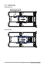
Page 32: ...System Hardware Installation 32 For GPU7 GPU8 1 2 2 For GPU1 GPU2 Front Rear 1 ...
Page 33: ... 33 System Hardware Installation 1 2 2 3 4 ...
Page 35: ... 35 System Hardware Installation 1 1 2 2 For GPU3 GPU4 1 1 2 2 3 4 ...
Page 37: ... 37 System Hardware Installation 3 4 5 6 6 ...
Page 39: ... 39 System Hardware Installation 5 6 ...
Page 41: ... 41 System Hardware Installation ...
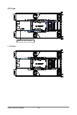
Page 48: ...System Hardware Installation 48 CPU Power MB Top Tray Connector 1 x 3 Power ...
Page 49: ... 49 System Hardware Installation HDD Backplane Board Signal HDD Backplane Board Power ...
Page 50: ...System Hardware Installation 50 Power Distribution Board to HDD Backplane Board Power SMD ...
Page 52: ...System Hardware Installation 52 Front Panel IO NVMe ...
Page 53: ... 53 System Hardware Installation NVMe Bo om Connector ...
Page 54: ...System Hardware Installation 54 NVMe Bo om Connector ...
Page 58: ...Motherboard Components 58 This page intentionally left blank ...
Page 82: ...BIOS Setup 82 5 2 13 SATA Configuration ...
Page 87: ... 87 BIOS Setup 5 2 18 Intel R I350 Gigabit Network Connection ...
Page 89: ... 89 BIOS Setup 5 2 19 VLAN Configuration ...
Page 93: ... 93 BIOS Setup 5 2 22 Intel R Ethernet Controller X550 ...


