15
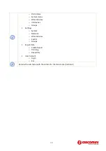
Figure 8 - Positive voltage digital input connection
•
Connect the common pole (negative) of the contact to the common terminal (7) of the device
•
Connect the positive pole of the contact to terminal (8)/(9)/(10) for inputs I1/I2/I3
When the voltage at the ends of the connected input – for example between (7) and (10) – ranges between
0V and 12V, the GE552Y051 input is considered open (
OFF
). When the voltage value ranges between 12V
and 24V, it is considered closed (
ON
).
5.1.8
Connecting the digital inputs to negative voltage contacts
Follow the instructions below to connect the digital inputs to the device with negative voltage (in the event
of closed contacts) and voltage free contacts (in the event of open contact):
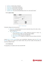
Figure 9 - Negative voltage digital input connection
•
Connect the common pole (positive) of the contact to the common terminal (7) of the device
•
Connect the negative pole of the contact to terminal (8)/(9)/(10) for inputs I1/I2/I3
When the voltage at the ends of the connected input – for example between (7) and (10) – ranges between
0V and 12V, the GE552Y051 input is considered open (
OFF
). When the voltage value ranges between 12V
and 24V, it is considered closed (
ON
).


