background image

44

Betriebsanleitung

Elektrischer Rückmelder Typ ER 52, ER 53

Ersatzteilliste und Zubehör

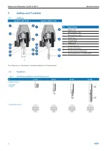
2

4

1

3

5

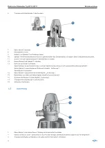
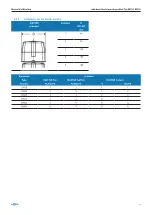
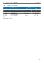
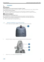
Pos.

Bezeichnung

ER 52-1/2

ER 52-3/4/5

ER 53-1/2/7

ER 53-3/4/5

1
2
3

Haubensatz
- Haube 
- Ring
- Schraube

198 000 217

198 000 213

4

Leitungsdose
- Leitungsdose
- Profildichtung

198 000 214

198 000 216

198 000 214

198 000 216

5

Adapter komplett*

199 190 310

Adapter
- Grösse 1 – 2
- Grösse 3
- Grösse 4 – 5 

199 190 387
199 190 388
199 190 389

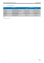
*Für Kombination ER 52/ER 53 / Hubgrenzung / Handnotbetätigung

Summary of Contents for ER 52

Page 1: ...Indicateur lectrique de posi tion Typ ER 52 ER 53 Manuel d utilisation Indicador de posici n el ctrico Tipo ER 52 ER 53 Manual de instrucciones 198150424 Electrical Position Indicator ER 52 ER 53 649...

Page 2: ...ntent Electrical Position Indicator Type ER 52 ER 53 3 Elektrischer R ckmelder Typ ER 52 ER 53 25 Indicateur lectrique de position Typ ER 52 ER 53 47 Indicador de posici n el ctrico Tipo ER 52 ER 53 6...

Page 3: ...GF Piping Systems Electrical Position Indicator Type ER 52 ER 53 Operating Instructions...

Page 4: ...ranteed properties nor guaranteed durability It is subject to modification Our General Terms of Sale apply Observe instruction manual The instruction manual is part of the product and an important ele...

Page 5: ...e instruction manual 9 2 3 Putting into operation use and disassembly only by qualified personnel 9 2 4 Storage and transport 9 2 5 General safety information 10 2 6 Product specific safety informatio...

Page 6: ...6 Operating Instructions Electrical Position Indicator Type ER 52 ER 53...

Page 7: ...e ER 52 DN 15 50 Type ER 53 DN 65 150 1 2 Scope of delivery The set includes Electrical Position Indicator type ER 52 ER 53 These operating instructions 1 3 Other applicable documents Other applicable...

Page 8: ...d below are in comp liance with the EMC Directive 2014 30 EU and meet such requirements The CE marking on the products indicates this compliance Changes to the products that affect the stated technica...

Page 9: ...3 Putting into operation use and disassembly only by qualified personnel Product and accessories should exclusively be put into operation or taken out of service by persons who have the necessary trai...

Page 10: ...here necessary 2 6 Product specific safety information WARNING Risk of injury due to high pressure in the system device Before working on the system or device switch off the pressure and vent drain th...

Page 11: ...radiation and temperature fluctuations can cause malfunctions or leaks Protect product from sun and weather conditions when used outdoors Observe permissible ambient temperatures NOTE Observe the res...

Page 12: ...ichnung 1 Cover SAN 2 Microswitch closed 3 Microswitch open 4 Cam PA 5 O rings NBR 6 Housing PP 7 Brass base 8 Spindle of stainless steel 9 Connecting piece of stainless steel 10 Unit plug 3P E DIN 43...

Page 13: ...3 2 2 Actuator sizes DIASTAR DN 15 50 DIASTAR size Size D PP GF mm 1 68 2 96 3 120 4 150 5 180 Dimension Size Type DIASTAR Ten DIASTAR TenPlus DIASTAR Sixteen Function FC DA FO FC DA FO FC DA FO DN15...

Page 14: ...oswitch AgNi 250 V 6 A 250 V 10 A ER 52 53 2 Microswitch with gold plated Au 4 30 V 1 100 mA 4 30 V 1 100 mA ER 52 53 3 Inductive switch NPN 10 30 V 0 1 A 9 6 55 V 0 2 A ER 52 53 4 Inductive switch PN...

Page 15: ...y regulations for electrical devices WARNING Risk of injury due to improper assembly Assembly may only be carried out by authorized specialist personnel using suitable tools Risk of injury due to unin...

Page 16: ...into the spindle nut of the actuator using an Allen key Observe left hand thread 10 Screw base 6 into actuator with wrench 11 Push lower cam 5 onto spindle 7 12 Push housing onto base 6 Position housi...

Page 17: ...en position using control pressure function DA only 1 2 Remove indicator cap 1 9 10 3 Screw the adapter 9 onto the locknut of the actuator 4 Type ER 53 Remove indicator cap Attention indicator pin has...

Page 18: ...g so that the electrical connection is in the desired position Pre position lower cam see chapter Adjustment Tighten threaded bolt 4 14 Pre position the upper cam 5 see chapter Adjustment 15 Connect t...

Page 19: ...for OPEN position 2 Normally open contact for CLOSED position 3 Power supply for both microswitches 5 1 2 Normally closed function NC Change connection No 4 on the microswitch wiring diagrams see cha...

Page 20: ...pe ER 52 ER 53 5 2 Wiring Diagrams ER 52 53 1 2 Type Code ER 52 1 199 190 305 ER 52 2 199 190 306 ER 53 1 199 190 293 ER 53 2 199 190 297 ER 52 3 4 Type Code ER 52 3 199 190 307 ER 52 4 199 190 308 ER...

Page 21: ...ons Electrical Position Indicator Type ER 52 ER 53 ER 52 5 Type Code ER 52 5 199 190 309 ER 53 5 Type Code ER 53 5 199 190 298 Output O 3 mA o 1 mA to DIN 19234 ER 52 53 6 Type Code ER 52 6 199 190 40...

Page 22: ...52 3 4 5 ER 53 1 2 7 ER 53 3 4 5 1 2 3 Cover set Cover O ring Screw 198 000 217 198 000 213 4 Unit plug Cable socket Profile washer 198 000 214 198 000 216 198 000 214 198 000 216 5 Adapter complete...

Page 23: ...ated components Parts of the product may be contaminated with media that are harmful for the health and the environment Therefore a simple cleaning is not sufficient Danger of personal injury and dama...

Page 24: ...ressed implied or warranted characteristics nor guaranteed properties or a guaranteed durability All Data is subject to modification The General Terms and Conditions of Sale of Georg Fischer Piping Sy...

Page 25: ...GF Piping Systems Elektrischer R ckmelder Typ ER 52 ER 53 Betriebsanleitung...

Page 26: ...r Haltbarkeits garantien nderungen vorbehalten Es gelten unsere Allgemeinen Verkaufsbedingungen Betriebsanleitung beachten Die Betriebsanleitung ist Teil des Produkts und ein wichtiger Baustein im Sic...

Page 27: ...sanleitung beachten 31 2 3 Inbetriebnahme Benutzung und Demontage nur durch Fachpersonal 31 2 4 Lagerung und Transport 31 2 5 Allgemeine Sicherheitshinweise 32 2 6 Produktspezifische Sicherheitshinwei...

Page 28: ...28 Betriebsanleitung Elektrischer R ckmelder Typ ER 52 ER 53...

Page 29: ...R 53 DN 65 150 1 2 Lieferumfang Im Set enthalten sind Elektrischer R ckmelder Typ ER 52 ER 53 Diese Bedienungsanleitung 1 3 Mitgeltende Dokumente Mitgeltende Unterlagen N Planungsgrundlagen Industrie...

Page 30: ...d solchen Anforderungen dieser Richtlinie entsprechen Die CE Kenn zeichnung an den Produkten zeigt diese bereinstimmung an nderungen an den Produkten die Auswirkungen auf die angegebenen technischen D...

Page 31: ...s weitergeben 2 3 Inbetriebnahme Benutzung und Demontage nur durch Fachpersonal Produkt und Zubeh r ausschliesslich von Personen in Betrieb oder ausserbetrieb setzen lassen welche die erforderliche Au...

Page 32: ...ktspezifische Sicherheitshinweise WARNUNG Verletzungsgefahr durch hohen Druck in Anlage Ger t Vor Arbeiten an Anlage oder Ger t den Druck abschalten und Leitungen entl ften entleeren Gefahr durch elek...

Page 33: ...hwankungen k nnen Fehlfunktionen oder Undichtheiten bewirken Produkt bei Einsatz im Aussenbereich vor Sonne und Witterungsverh ltnissen sch tzen Zul ssige Umgebungstemperaturen beachten HINWEIS Best n...

Page 34: ...Haube SAN 2 Mikroschalter Zu 3 Mikroschalter Auf 4 Nocken PA 5 O Ringe NBR 6 Geh use PP 7 Sockel Messing 8 Spindel ST Rostfrei 9 Anschlussst ck ST Rostfrei 10 Ger testecker 3P E DIN 43650 Durchmesser...

Page 35: ...riebsgr ssen DIASTAR DN 15 50 DIASTAR Gr sse Gr sse D PP GF mm 1 68 2 96 3 120 4 150 5 180 Dimension Gr sse Typ DIASTAR Ten DIASTAR TenPlus DIASTAR Sixteen Funktion FC DA FO FC DA FO FC DA FO DN15 1 2...

Page 36: ...r AgNi 250 V 6 A 250 V 10 A ER 52 53 2 Mikroschalter mit Goldkontakt Au 4 30 V 1 100 mA 4 30 V 1 100 mA ER 52 53 3 Induktiv Schalter NPN 10 30 V 0 1 A 9 6 55 V 0 2 A ER 52 53 4 Induktiv Schalter PNP 1...

Page 37: ...elektrische Ger te beachten WARNUNG Verletzungsgefahr bei unsachgem sser Montage Die Montage darf nur autorisiertes Fachpersonal mit geeignetem Werkzeug durchf hren Verletzungsgefahr durch ungewolltes...

Page 38: ...schrauben Dabei Linksgewinde beachten 10 Sockel 6 mit Schraubenschl ssel in Stellantrieb schrauben 11 Untere Nocke 5 auf Spindel 7 schieben 12 Geh use auf Sockel 6 schieben Dabei Geh use so positionie...

Page 39: ...erdruck in Stellung Nur Funktion DA 1 2 Anzeigekappe 1 demontieren 9 10 3 Adapter 9 auf Sicherungsmutter am Stellantrieb schrauben 4 Bei ER 53 Anzeigestift demontieren Dabei Linksgewinde des Anzeigest...

Page 40: ...ren dass sich der elektrische Anschluss in der gew nschten Stellung befindet Untere Nocke 5 vorpositionieren Siehe auch Kapitel Justierung Gewindestift 4 festziehen 14 Obere Nocke 5 vorpositionieren S...

Page 41: ...r ZU Position 3 Speisung f r beide Mikroschalter 5 1 2 ffnerfunktion NC Anschl sse an den Mikroschaltern uml ten Anschlussschaltbilder siehe Kapitel 5 2 Anschluss Nr 2 belegen 5 1 3 Wechslerfunktion...

Page 42: ...2 ER 53 5 2 Anschlusschaltbilder ER 52 53 1 2 Typ Code ER 52 1 199 190 305 ER 52 2 199 190 306 ER 53 1 199 190 293 ER 53 2 199 190 297 ER 52 3 4 Typ Code ER 52 3 199 190 307 ER 52 4 199 190 308 ER 53...

Page 43: ...tung Elektrischer R ckmelder Typ ER 52 ER 53 ER 52 5 Typ Code ER 52 5 199 190 309 ER 53 5 Typ Code ER 53 5 199 190 298 Ausgang O 3 mA o 1 mA nach DIN 19234 ER 52 53 6 Typ Code ER 52 6 199 190 405 ER 5...

Page 44: ...ER 53 1 2 7 ER 53 3 4 5 1 2 3 Haubensatz Haube Ring Schraube 198 000 217 198 000 213 4 Leitungsdose Leitungsdose Profildichtung 198 000 214 198 000 216 198 000 214 198 000 216 5 Adapter komplett 199 1...

Page 45: ...s Produkts k nnen mit gesundheits und umweltsch dlichen Medien kontaminiert sein so dass eine einfache Reinigung nicht ausreichend ist Gefahr von Personen oder Umweltsch den durch diese Medien Vor der...

Page 46: ...nd technischen Daten insgesamt Daten sind nicht verbindlich sofern sie nicht ausdr cklich schriftlich best tigt werden Die Daten begr nden weder ausdr ckliche stillschweigende oder zugesicherte Merkma...

Page 47: ...GF Piping Systems Indicateur lectrique de po sition Typ ER 52 ER 53 Manuel d utilisation...

Page 48: ...ou de durabilit Sous r serve de modifications Nos conditions g n rales de vente s appliquent Se reporter au manuel d utilisation Le manuel d utilisation fait partie int grante du produit et constitue...

Page 49: ...ilisation 53 2 3 Mise en service utilisation et d montage r serv s un personnel sp cialis 53 2 4 Transport et stockage 53 2 5 Consignes de s curit g n rales 54 2 6 Consignes de s curit sp cifiques au...

Page 50: ...50 Manuel d utilisation Indicateur lectrique de position Typ ER 52 ER 53...

Page 51: ...vantes Type ER 52 DN 15 50 Type ER 53 DN 65 150 1 2 Contenu de la livraison Le kit contient Indicateur lectrique de position type ER 52 ER 53 Le pr sent manuel d utilisation 1 3 Documents applicables...

Page 52: ...ent la directive CEM 2014 30 UE et se conforment aux exigences de cette directive Le marquage CE sur les produits t moi gne de cette conformit Toute modification apport e aux produits qui affecte les...

Page 53: ...ssifs du produit 2 3 Mise en service utilisation et d montage r serv s un personnel sp cialis Les produits et accessoires doivent exclusivement tre mis en marche ou hors service par des personnes qui...

Page 54: ...nt et les remplacer le cas ch ant 2 6 Consignes de s curit sp cifiques au produit AVERTISSEMENT Risque de blessures d la pression lev e dans l installation l appareil Avant d effectuer des travaux sur...

Page 55: ...uvent occasionner des dysfonctionnements ou des d fauts d tanch i t Prot ger le produit du soleil et des conditions m t orologiques en cas d utilisation en ext rieur Tenir compte des temp ratures ambi...

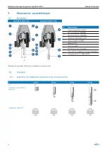
Page 56: ...contacteur FERME 3 Microcontacteur OUVERT 4 Came de commande en PA 5 Joints toriques en NBR 6 Bo tier en PP 7 Socle en laiton 8 Broche en acier inoxydable 9 Pi ce de raccordement en acier inoxydable 1...

Page 57: ...2 Grandeurs du servom canisme DIASTAR grandeur Grandeur D PP GF mm 1 68 2 96 3 120 4 150 5 180 Dimension Grandeur Type DIASTAR Ten DIASTAR TenPlus DIASTAR Sixteen Fonction FC DA FO FC DA FO FC DA FO D...

Page 58: ...ocontacteur AgNi 250 V 6 A 250 V 10 A ER 52 53 2 Microcontacteur contacts or Au 4 30 V 1 100 mA 4 30 V 1 100 mA ER 52 53 3 Contacteur inductif NPN 10 30 V 0 1 A 9 6 55 V 0 2 A ER 52 53 4 Contacteur in...

Page 59: ...s applicables pour les appareils lectriques AVERTISSEMENT Risque de blessures en cas de montage incorrect Le montage doit exclusivement tre r alis par des techniciens autoris s avec des outils appropr...

Page 60: ...s creux Tenir compte du filetage gauche 10 Visser le socle 6 avec une cl dans le servom canisme 11 Faire glisser la came inf rieure 5 sur la tige7 12 Faire glisser le bo tier sur le socle 6 Positionne...

Page 61: ...RT au moyen de la pression de commande DA 1 2 D monter le capot de l indicateur 1 9 10 3 Visser l adaptateur 9 sur l crou de s curit sur le servom canisme 4 Type ER 53 D montage de l indicateur de pos...

Page 62: ...ositionner le bo tier de mani re ce que le raccordement lectrique se trouve dans la position souhait e Pr positionner la came inf rieure 5 voir aussi le chapitre Ajustage Serrer bloc la vis sans t te...

Page 63: ...VERT 2 Contact de travail pour position FERME 3 Alimentation pour les deux microcontacteurs 5 1 2 Fonction de contact de repos Changer les raccordements sur les microcontacteurs Utiliser raccordement...

Page 64: ...R 52 ER 53 5 2 Sch mas de raccordement ER 52 53 1 2 Type Code ER 52 1 199 190 305 ER 52 2 199 190 306 ER 53 1 199 190 293 ER 53 2 199 190 297 ER 52 3 4 Type Code ER 52 3 199 190 307 ER 52 4 199 190 30...

Page 65: ...Indicateur lectrique de position Typ ER 52 ER 53 ER 52 5 Type Code ER 52 5 199 190 309 ER 53 5 Type Code ER 53 5 199 190 298 Sortie O 3 mA o 1 mA selon DIN 9234 ER 52 53 6 Type Code ER 52 6 199 190 4...

Page 66: ...3 4 5 1 2 3 Ensemble capot Capot Joint torique Vis t te cylindrique 198 000 217 198 000 213 4 Connecteur Connecteur Joint profil 198 000 214 198 000 216 198 000 214 198 000 216 5 Adaptateur complet 19...

Page 67: ...AVERTISSEMENT Composants contamin s Les pi ces du produit peuvent tre contamin es avec des fluides nocifs pour la sant et pour l environnement de sorte qu un simple nettoyage n est pas suffisant Risqu...

Page 68: ...cite des caract ristiques et ne garantissent pas des propri t s sp cifiques ou une durabilit Toutes les donn es sont sujettes modification Les conditions g n rales et les conditions de vente de Georg...

Page 69: ...GF Piping Systems Indicador de posici n el c trico Tipo ER 52 ER 53 Manual de instrucciones...

Page 70: ...a modificaciones Son v lidas nuestras Condiciones Generales de Venta Obs rvese el manual de instrucciones El manual de instrucciones forma parte del producto y es un elemento importante del concepto d...

Page 71: ...75 2 3 Puesta en funcionamiento uso y desmontaje solo por parte del personal t cnico 75 2 4 Almacenamiento y transporte 75 2 5 Advertencias de seguridad generales 76 2 6 Advertencias de seguridad espe...

Page 72: ...72 Manual de instrucciones Indicador de posici n el ctrico Tipo ER 52 ER 53 7 Eliminaci n 89...

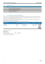
Page 73: ...nsiones Tipo ER 52 DN 15 50 Tipo ER 53 DN 65 150 1 2 Contenido El set incluye Indicador de posici n el ctrico tipo ER 52 ER 53 Este manual de instrucciones 1 3 Documentaci n complementaria Documentaci...

Page 74: ...indicados a continua ci n cumplen con la Directiva CEM 2014 30 UE y los requisitos de dicha directiva La marca CE en los productos indica dicha conformidad Toda modificaci n de los productos que afect...

Page 75: ...ios 2 3 Puesta en funcionamiento uso y desmontaje solo por parte del personal t cnico Encomendar la puesta en funcionamiento y la puesta fuera de servicio del producto y los accesorios nicamente a per...

Page 76: ...gularidad y sustituirlas si es necesario 2 6 Advertencias de seguridad espec ficas del producto ADVERTENCIA Riesgo de lesiones por alta presi n en la instalaci n el aparato Antes de trabajar en la ins...

Page 77: ...ones de temperatura pueden provocar aver as o fugas Proteger el producto del sol y las inclemencias del tiempo en caso de uso en el exterior Respetar las temperaturas ambiente permitidas NOTA Tener en...

Page 78: ...rruptor cerrado 3 Microinterruptor abierto 4 Levas PA 5 Anillos t ricos NBR 6 Carcasa PP 7 Z calo lat n 8 Husillo ST inoxidable 9 Pieza de empalme ST inoxidable 10 Conector del aparato 3P E DIN 43650...

Page 79: ...2 Tama os de actuador DIASTAR DN 15 50 DIASTAR tama o Tama o D PP GF mm 1 68 2 96 3 120 4 150 5 180 Dimensi n Tama o Tipo DIASTAR Ten DIASTAR TenPlus DIASTAR Sixteen Funci n FC DA FO FC DA FO FC DA F...

Page 80: ...r AgNi 250 V 6 A 250 V 10 A ER 52 53 2 Microinterruptor con contacto de oro Au 4 30 V 1 100 mA 4 30 V 1 100 mA ER 52 53 3 Interruptor inductivo NPN 10 30 V 0 1 A 9 6 55 V 0 2 A ER 52 53 4 Interruptor...

Page 81: ...ara aparatos el ctricos ADVERTENCIA Riesgo de lesiones en caso de ensamblaje inadecuado nicamente personal especializado autorizado con las herramientas adecuadas puede completar el ensamblaje Riesgo...

Page 82: ...una llave tornillos Observa la rosca de la izquierda 10 Atornilla el z calo 6 en el actuador con la llave 11 Empuja la leva inferior 5 sobre el husillo 7 12 Empuja la carcasa sobre el z calo 6 Coloca...

Page 83: ...ol en posici n abierta Funci n DA 1 2 Desmontar el tap n indicador 1 9 10 3 Enroscar el adaptador 9 a la contratuerca del actuador 4 En el tipo ER 53 Desmontar el perno indicador Tener en cuenta que e...

Page 84: ...i n el ctrica est en la posici n deseada Preposicionar la leva inferior 5 ver tambi n el cap tulo Ajuste Apriete el tornillo roscado 4 14 Coloque previamente la leva superior 5 v ase el cap tulo Ajust...

Page 85: ...aci n para ambos microinterruptores 5 1 2 Funci n de contacto normalmente cerrado Soldar las conexiones a los microinterruptores v anse los esquemas de conexiones en el cap tulo 5 2 Asignar la conexi...

Page 86: ...ER 52 ER 53 5 2 Esquemas de conexiones ER 52 53 1 2 Tipo Code ER 52 1 199 190 305 ER 52 2 199 190 306 ER 53 1 199 190 293 ER 53 2 199 190 297 ER 52 3 4 Tipo Code ER 52 3 199 190 307 ER 52 4 199 190 3...

Page 87: ...Indicador de posici n el ctrico Tipo ER 52 ER 53 ER 52 5 Tipo Code ER 52 5 199 190 309 ER 53 5 Tipo Code ER 53 5 199 190 298 Salida O 3 mA o 1 mA conforme a DIN 19234 ER 52 53 6 Tipo Code ER 52 6 199...

Page 88: ...4 5 1 2 3 Juego de cubiertas Cubierta Anillo Tornillo 198 000 217 198 000 213 4 Conector de cable Conector de cable Junta de perfil 198 000 214 198 000 216 198 000 214 198 000 216 5 Adaptador completo...

Page 89: ...minados Algunas partes del producto pueden estar contaminadas con fluidos nocivos para la salud y el medio ambiente y por tanto no bas ta simplemente con limpiarlas Estos fluidos pueden causar da os p...

Page 90: ...as expl citas impl citas o garantizadas propiedades garantizadas o una garant a de durabilidad Todos los datos est n sujetos a modificaciones Se aplican las Condiciones Generales de Venta de Georg Fis...

Reviews: