18
Operating Instructions
Electrical Position Indicator Type ER 52, ER 53
6.
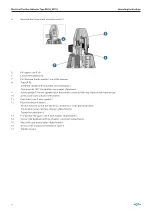
Unscrew the transparent protective cover 3.
4
5
6
7
7.
Pull upper cam 5 off.
8.
Loosen threaded bolt 4.
9.
Pull the base 6 with spindle 7 out of the housing.
10.
Screw spindle 7 into the spindle nut of the actuator using an Allen key. Observe left-hand thread.
11.
Screw base 6 into actuator with wrench.
12.
Push lower cam 5 onto spindle 7.
13.
Push housing onto base 6:
•
Position housing so that the electrical connection is in the desired position.
•
Pre-position lower cam (see chapter «Adjustment»).
•
Tighten threaded bolt 4.
14.
Pre-position the upper cam 5 (see chapter «Adjustment»).
15.
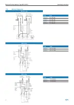
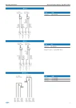
Connect the feedback unit (see chapter «Electrical connections»).
16.
Adjust the cam (see chapter «Adjustment»).
17.
Screw on the transparent protective cover 3.
18.
Tighten screw 2.
4.3
Adjustment
2
8
7
1
1.
Slide the upper cam 2 and the lower cam 7 flush against the adjustment plate 8.
2.
Put the valve once in the «open» and once in the «closed» position The cams are hereby correctly adjusted.
3.
Screw the transparent cover back on the housing and tighten with the screw 1.
Summary of Contents for ER 52
Page 3: ...GF Piping Systems Electrical Position Indicator Type ER 52 ER 53 Operating Instructions...
Page 6: ...6 Operating Instructions Electrical Position Indicator Type ER 52 ER 53...
Page 25: ...GF Piping Systems Elektrischer R ckmelder Typ ER 52 ER 53 Betriebsanleitung...
Page 28: ...28 Betriebsanleitung Elektrischer R ckmelder Typ ER 52 ER 53...
Page 47: ...GF Piping Systems Indicateur lectrique de po sition Typ ER 52 ER 53 Manuel d utilisation...
Page 50: ...50 Manuel d utilisation Indicateur lectrique de position Typ ER 52 ER 53...
Page 69: ...GF Piping Systems Indicador de posici n el c trico Tipo ER 52 ER 53 Manual de instrucciones...
Page 72: ...72 Manual de instrucciones Indicador de posici n el ctrico Tipo ER 52 ER 53 7 Eliminaci n 89...


