19
Operating Instructions
Electrical Position Indicator Type ER 52, ER 53
5
Electrical Connections
5.1
Connect unit plug
5.1.1
Normally open function (NO)
►
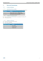
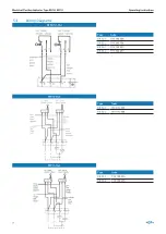
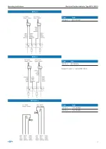
Connect the position indicator with the unit plug, wiring diagrams see chapter 5.2
Connection
Function
1
Normally open contact for «OPEN» position
2
Normally open contact for «CLOSED» position
3
Power supply for both microswitches
5.1.2
Normally closed function (NC)
►
Change connection No 4 on the microswitch, wiring diagrams see chapter 5.2
►
Connect connection No 2.
5.1.3
Change-over function
►
Remove the unit plug and the internal wiring
►
Install a PG11 cable gland.
►
Connect multiple wires directly to the microswitch connector lug.
Plat pin microswitches
Function
1
Power supply
2
Normally closed
4
Normally open
Summary of Contents for ER 52
Page 3: ...GF Piping Systems Electrical Position Indicator Type ER 52 ER 53 Operating Instructions...
Page 6: ...6 Operating Instructions Electrical Position Indicator Type ER 52 ER 53...
Page 25: ...GF Piping Systems Elektrischer R ckmelder Typ ER 52 ER 53 Betriebsanleitung...
Page 28: ...28 Betriebsanleitung Elektrischer R ckmelder Typ ER 52 ER 53...
Page 47: ...GF Piping Systems Indicateur lectrique de po sition Typ ER 52 ER 53 Manuel d utilisation...
Page 50: ...50 Manuel d utilisation Indicateur lectrique de position Typ ER 52 ER 53...
Page 69: ...GF Piping Systems Indicador de posici n el c trico Tipo ER 52 ER 53 Manual de instrucciones...
Page 72: ...72 Manual de instrucciones Indicador de posici n el ctrico Tipo ER 52 ER 53 7 Eliminaci n 89...

