17
Operating Instructions
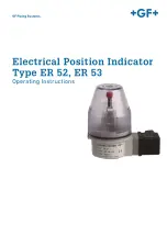
Electrical Position Indicator Type ER 52, ER 53
4.2
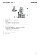
Diaphragm Valve with Stroke Limiter
1. Put valve in the «open» position using control pressure (function DA only)
1
2.
Remove indicator cap 1.
9
10
3.
Screw the adapter 9 onto the locknut of the actuator.
4.
Type ER 53:
•
Remove indicator cap. (Attention: indicator pin has left thread.)
•
Screw the intermediate piece 10 into the connecting piece.
3
2
4
5.
Loosen the screw 2 on the electrical position indicator.
Summary of Contents for ER 52
Page 3: ...GF Piping Systems Electrical Position Indicator Type ER 52 ER 53 Operating Instructions...
Page 6: ...6 Operating Instructions Electrical Position Indicator Type ER 52 ER 53...
Page 25: ...GF Piping Systems Elektrischer R ckmelder Typ ER 52 ER 53 Betriebsanleitung...
Page 28: ...28 Betriebsanleitung Elektrischer R ckmelder Typ ER 52 ER 53...
Page 47: ...GF Piping Systems Indicateur lectrique de po sition Typ ER 52 ER 53 Manuel d utilisation...
Page 50: ...50 Manuel d utilisation Indicateur lectrique de position Typ ER 52 ER 53...
Page 69: ...GF Piping Systems Indicador de posici n el c trico Tipo ER 52 ER 53 Manual de instrucciones...
Page 72: ...72 Manual de instrucciones Indicador de posici n el ctrico Tipo ER 52 ER 53 7 Eliminaci n 89...

