12
Operating Instructions
Electrical Position Indicator Type ER 52, ER 53
3
Design and function
3.1
Design
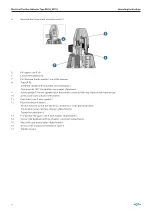
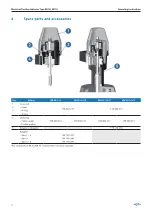
Type ER 52 (DN 15-50)
Type ER 53 (DN 65-150)
1
3
5
10
6
7
9
8
4
2 1
3
5
10
6
7
9
8
4
2
Nr.
Bezeichnung
1
Cover SAN
2
Microswitch «closed»
3
Microswitch «open»
4
Cam PA
5
O-rings NBR
6
Housing PP
7
Brass base
8
Spindle of stainless steel
9
Connecting piece of stainless steel
10
Unit plug 3P + E / DIN 43650
*Diameter d, see table „Allocation of adapter to actuator sizes“
3.2
Function
3.2.1
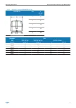
Allocation of adapter to actuator sizes
d
12 mm
16 mm
16 mm
16 mm
Actuator size
1/2
3
4
5
Required
Brass base (7)
Summary of Contents for ER 52
Page 3: ...GF Piping Systems Electrical Position Indicator Type ER 52 ER 53 Operating Instructions...
Page 6: ...6 Operating Instructions Electrical Position Indicator Type ER 52 ER 53...
Page 25: ...GF Piping Systems Elektrischer R ckmelder Typ ER 52 ER 53 Betriebsanleitung...
Page 28: ...28 Betriebsanleitung Elektrischer R ckmelder Typ ER 52 ER 53...
Page 47: ...GF Piping Systems Indicateur lectrique de po sition Typ ER 52 ER 53 Manuel d utilisation...
Page 50: ...50 Manuel d utilisation Indicateur lectrique de position Typ ER 52 ER 53...
Page 69: ...GF Piping Systems Indicador de posici n el c trico Tipo ER 52 ER 53 Manual de instrucciones...
Page 72: ...72 Manual de instrucciones Indicador de posici n el ctrico Tipo ER 52 ER 53 7 Eliminaci n 89...

