21
GEZE
Planungsunterlage TSA160 Datei 84338PuTSA160_GB_200999_.p65
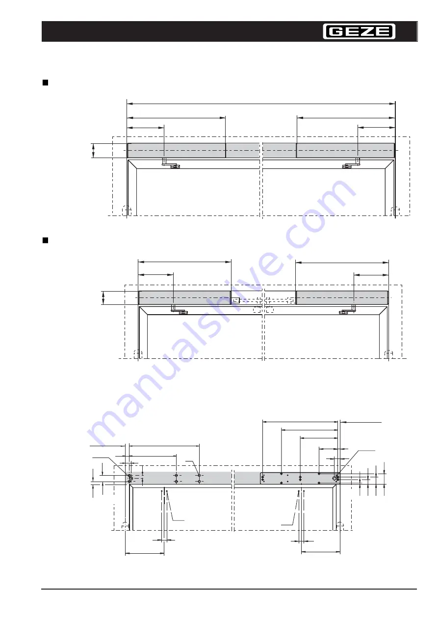
B min = 1470
B max = 2800
260
260
690
690
100
650
487,5
325
M6
M6
50
335
44
335
44
162,5 20
*1)
*1)
90
61
39
10
M6
625
50
27
54
23
34
420
TSA 160 F-IS incl. integrated closing sequence control
TSA 160 F incl. external closing sequence control
hinge centre
hinge centre
*1) If cable entry is from the rear, make boring Ø 20
Mounting dimensions DIN right pushing
(Dimensions for direct fixing)
Mounting dimensions DIN left pushing
(Dimensions incl. mounting plate)
Drive opposite hinge side
Drive opposite hinge side
Mounting dimensions when mounting plate is used
690
260
690
260
100


