


IQ lock AUT, EL / EL DL, EM / EM DL, C / C DL, M / M DL
52
Wiring diagrams
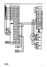
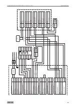
6.19 IQ lock AUT with TSA160 NT (-F, -I) and activation
X
Follow the mechanical installation instructions for IQ lock.
X
Heed the wiring diagram for TSA160 NT, TSA160 NT-F, TSA160 NT Invers.
Disconnect the internal programme switch of the door drive.
For 2-leaf door drives connect the control to the active leaf.
Set the parameters on the control unit DCU5 as follows:
X
With DPS:
à
Set parameter
rr
(
21
)(bar message) to
02
(electric strike) and
to
(
20
) (electric strike type) to
03
(motor lock).
X
With ST220:
à
Set Input signals
Bar message to electric strike.
à
Set Door parameters
Electric strike type to motor lock.
Voltage supply of the MST 210 from separate power supply NT 19.2-24 or from the DCU5 control.
The GND of DCU5 (terminal TOE no. 1) must be connected with the GND of the MST 210 (terminal X7 no. 1), even
when a separate power supply is used.
Voltage supply of the rod drive IQ AUT from separate 24 V DC 1.5 A power supply.
The day function on the lock cannot be used with analogue programme switches (DPS / TPS / MPS).
Summary of Contents for IQ lock AUT
Page 56: ...IQ lock AUT EL EL DL EM EM DL C C DL M M DL 56 Wiring diagrams ...
Page 66: ...IQ lock AUT EL EL DL EM EM DL C C DL M M DL 66 Annex ...
Page 68: ...IQ lock AUT EL EL DL EM EM DL C C DL M M DL 68 Annex ...
Page 70: ...IQ lock AUT EL EL DL EM EM DL C C DL M M DL 70 Annex ...
Page 71: ...IQ lock AUT EL EL DL EM EM DL C C DL M M DL 71 Annex ...


