background image

IQ lock AUT, EL / EL DL, EM / EM DL, C / C DL, M / M DL

25

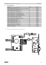
Wiring diagrams

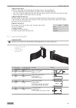
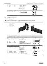
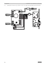
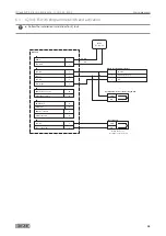
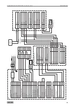
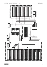
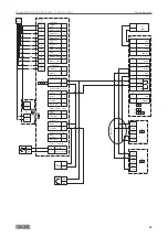
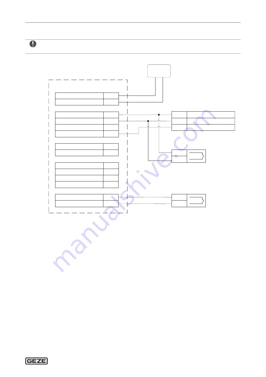
6.3  IQ lock EL with programme switch and activation


X

Follow the installation instructions for IQ lock.

Permanently open

2

Day

3

24 V DC

1

1

2

7

8

MPS-D /potentialfreier Schalter

24 V DC in

3

24 V DC

Release 

24 V DC

Day / Night


2

5

2

4

COM Cylinder contact

NO Cylinder contact

24

25

X6

X8

MST 210

24V DC

NT 19.2-24

RD

GND in

1

X7

BK / RD

COM Door handle

NO Door handle

17

16

X2

24 V DC

Door contact (IN)

2

6

X5

COM Release

NO Release

12

13

COM

NO

Door contact

COM

NO

Push button / Access control / Key switch

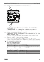
When the door is 

closed the contact is closed

Summary of Contents for IQ lock AUT

Page 1: ...157720 04 IQ lock self locking panic locks for 1 and 2 leaf doors IQ lock AUT IQ lock EL IQ lock EL DL IQ lock EM IQ lock EM DL IQ lock C IQ lock C DL EN Commissioning and connection instructions ...

Page 2: ...th IQ lock EL IQ lock EL DL 12 5 2 Rod drive IQ AUT 19 5 3 Lever lock IQ lock EM 21 5 4 Contact lock IQ lock C 22 6 Wiring diagrams 23 6 1 IQ lock EL with motor lock control MST 210 23 6 2 Standard connection IQ LOCK EL MST 210 with low pass filter from HW 159073 24 6 3 IQ lock EL with programme switch and activation 25 6 4 IQ lock EL with EMD F I and activation 26 6 5 IQ lock EL with EMD F I TZ 3...

Page 3: ... defined in the German Product Liability Act compliance with the information contained in this brochure product information and intended use misuse product performance product maintenance obligations to provide information and instructions must be ensured Failure to comply releases the manufacturer from his statutory liability Abbreviations VB Solid leaf RR Tubular frame 6 17 IQ lock AUT with K600...

Page 4: ...the product Trouble free functioning of the locks is only ensured if a carry bar and a door closer system in accordance with EN 1158 with closing sequence control are mounted Before mounting the emergency exit locks ensure that the door is fitted properly and not distorted in any way X X Install the emergency exit locks only in hollow doors that are designed for this purpose by the manufacturer Th...

Page 5: ... by GEZE Lubricant Manufacturer Note Klübersynth LI 44 22 Klüber Lubrication Slightly wet the latch and crossbar Fin Lube TF Interflon Spray onto the latch and crossbar from the outside 1 5 Accessories GEZE self locking panic locks may only be used with the accessories prescribed by GEZE X X Only use genuine GEZE accessories à à If other parts are attached or installed any warranty guarantee and o...

Page 6: ...ed detectors and 1 lintel mounted detector are required This corresponds to 2 ceiling mounted detectors and 1 smoke switch control unit The smoke switch control unit RSZ 5 and RSZ 6 includes power supply 1 lintel mounted detector is connected directly to the MST in accordance with wiring diagram 1 7 3 Motor lock in night mode of operation The motor lock is used in night mode of operation only In t...

Page 7: ...ent of a power failure Automatic resetting of the release if door is not opened Input for fire alarm system locking Unlocking by key Operating voltage 24 V 12 24 V 12 V 24 V 48 V Feedback contacts for lock states Optional sabotage monitoring or cylinder contact Can be used on the left and right Same installation dimensions for all IQ locks Backset 35 40 45 55 60 65 70 80 100 Distance 72 74 78 92 9...

Page 8: ...operation and secured daytime operation secured by day mode of operation the third mode of operation permanently unlocked is possible see Setting permanently unlocked chapter 5 1 Here the crossbar is retracted and the cross latches are unstable The door can be pulled or pushed open at any time by hand Exception In the event of a fire the door is locked completely after the door leaf has closed The...

Page 9: ... at 12 V DC max 1 A briefly at 12 V DC 80 mA at 24 V DC max 500 mA briefly at 24 V DC incl MST 210 Current consumption IQ lock EM 350 mA at 12 V DC 210 mA at 24 V DC 105 mA at 48 V DC Max contact rating of the relays 30 V DC 500 mA Resistance to forcing 10 000 N Technical specification à à Perfectly closing doors with door closer à à Always use genuine GEZE strike plate à à Clearance between face ...

Page 10: ...spheres Approvals à à EN 179 Emergency exit devices à à EN 1125 Panic exit devices à à EN 1634 Fire resistance and smoke protection test à à CE 4 3 Power supply NT 19 2 24 ID No 089862 Function Power supply for IQ lock EL IQ lock EL DL Dimensions 92 32 32 mm W H D Operating voltage à à Primary 230 V AC current consumption 250 mA à à Secondary 24 V DC current output 800 mA 19 2 W IP rating IP54 4 4...

Page 11: ...e 10 50 C Version Top hat rail casing 4 7 Motor lock control MST 210 X X Follow the mechanical installation instructions for motor lock IQ lock ID No 103671 Function Control unit for motor lock IQ lock EL IQ lock EL DL Dimensions 140 140 79 mm W H D Weight 0 3 kg Operating voltage 12 24 V DC 10 15 Current consumption à à 160 mA at 12 V DC à à max 1 A briefly at 12 V DC à à 80 mA at 24 V DC à à max...

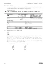
Page 12: ...L 5 1 1 Connections X10 Cover monitoring OUT 23 NC 22 COM X8 Cylinder contact Sabotage OUT 25 NO NC 24 COM X5 Door contact IN 6 NO NC 2 24V ext X4 Smoke detector IN 9 NC 8 COM X X A jumper must be inserted if no smoke detector is used See the following pages for further application options 24V X3 Bolt switching contact OUT 21 COM 20 NO X6 Mode of operation IN 4 Day night 2 24V ext 5 Release 2 24V ...

Page 13: ...x 1 s 2 ON x 2 s 3 ON x 5 s 4 ON x 10 s Example Set release time 9 s Release times of 1 19 s can thus be set with a pulse control of the release input terminals X6 2 and X6 5 If a longer release time or continuous release is required this is to be realised by a correspondingly long actuation time or a continuous contact Setting of the release time is also used to set the duration of the contacting...

Page 14: ...ng MST 210 NC Casing cover monitoring closes a contact when the casing cover of the MST 210 is opened X10 22 Cover monitoring MST 210 COM Setting daytime operation If the contact between terminals X6 2 and X6 4 is closed permanent contact the lock runs in daytime operation If the contact is opened the lock runs in night time operation This means that the lock automatically locks every time the doo...

Page 15: ...black cables are not connected directly to the motor lock control MST 210 they are connected with terminal X12 of the additional PCB TPF The TPF has been optimised for the new motor drive unit in the lock and for the new software see chapter 5 1 4 and chapter 5 1 6 Taking the conditions listed in chapter 5 1 7 into account the TPF can also be used for locks with an older building design Insert TPF...

Page 16: ...k IQ lock EL IQ lock EL DL to terminal X1 of the motor lock control MST 210 23 22 X10 24 25 X8 2 6 X5 8 9 X4 20 21 X3 5 2 X6 4 2 3 1 X7 12 13 X2 10 11 16 17 14 15 18 19 2 31 X1 27 28 34 35 32 33 38 39 36 37 JP1 JP2 F1 F2 X9 X11 LED1 ON 1 2 3 4 LED6 LED5 LED4 LED3 LED2 X13 X11 27 28 X12 27 28 BK RD Cable IQ lock EL Cable IQ lock EL DL 5 1 4 Motor lock control MST 210 with new software from version ...

Page 17: ...ion take the respective combination possibilities between old and new products as listed in chapter 5 1 7 into account 5 1 7 Combination possibilities between old and new components Due to the changes described in chapters 5 1 3 to 5 1 6 different combination possibilities can occur For you to be able to identify the optimum solution for your application the following table lists the combination p...

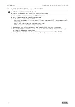
Page 18: ...ltage Jumper position JP2 Description 12 V operating voltage 24 V operating voltage Fuses Description Value Description F1 1 A SMF 125 V fast acting Input fuse 24 V internal F2 1 A SMF 125 V fast acting Fuse for smoke detector external supply 5 1 9 Sabotage monitoring or cylinder contact 24 25 A switch see chapters 6 4 1 and 6 4 2 on the motor lock is used to select between the operating modes sab...

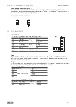
Page 19: ...20 white WH Output 1 Output 1 locked X1 21 grey GY Com X1 22 pink PK Output 2 Unlocked X1 21 grey GY Com 22 21 20 42 41 X1 X5 X4 5 2 3 1 41 42 43 2 1 Input A potential free contact normally opened contact must be connected to pins X1 2 and X1 5 If the contact is actuated IQ AUT moves to the unlocked position where it remains for the hold open time The time starts once the contact has been disconne...

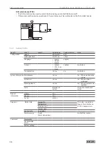
Page 20: ... English à à French à à English English Output 1 à à Locked à à SW 6 sec à à Alarm Locked See below Fire protection Yes no no See below System information Maintenance Yes no Yes When maintenance is due System init Yes no Yes When system is initialised Motor replaced Yes no Yes When the motor was replaced Cycle Number of cycles The current number of cycles Product information HW ver Vx x SW ver Vx ...

Page 21: ... drive IQ AUT has 5 sensors inside This menu shows which sensor is currently active To update the table X X Keep the Enter key pressed This menu is relevant for service technicians Rod Wheel Lckd Unlckd 1 Unlckd 2 5 3 Lever lock IQ lock EM Connection cable If polarity is reversed the outside handle cannot be engaged reverse polarity protection 1 Connector IQ lock EM IQ lock EM DL 2 Connector power...

Page 22: ...polarity protection 1 Connector IQ lock C IQ lock C DL 2 Connector power supply cable 6 12 1 7 6 12 7 1 PIN Connector IQ lock C 1 Connector power supply cable 2 Function Contact 3 blue blue Door handle contact NO Contact closed Door handle actuated PIN 7 PIN 3 7 green green 5 grey grey Auxiliary latch NO Contact closed Auxiliary latch actuated door closed PIN 8 PIN 5 8 brown brown 9 white white De...

Page 23: ...d smoke switch control unit 6 8 Page 34 IQ lock EL with TSA160 NT F I smoke switch control unit 6 9 Page 35 IQ lock EL with smoke switch control unit RSZ 6 6 10 Page 36 IQ lock EL with smoke switch control unit RSZ 5 6 11 Page 37 IQ lock EL with smoke switch control unit FA GC 150 160 6 12 Page 38 IQ lock EL with TZ 320 SN and activation 6 13 Page 40 IQ lock EL with K600 and activation 6 14 Page 4...

Page 24: ...IQ lock AUT EL EL DL EM EM DL C C DL M M DL 24 Wiring diagrams 6 2 Standard connection IQ LOCK EL MST 210 with low pass filter from HW 159073 ...

Page 25: ...1 2 7 8 MPS D potentialfreier Schalter 24 V DC in 3 24 V DC Release 24 V DC Day Night 2 5 2 4 COM Cylinder contact NO Cylinder contact 24 25 X6 X8 MST 210 24V DC NT 19 2 24 RD GND in 1 X7 BK RD COM Door handle NO Door handle 17 16 X2 24 V DC Door contact IN 2 6 X5 COM Release NO Release 12 13 COM NO Door contact COM NO Push button Access control Key switch When the door is closed the contact is cl...

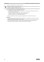
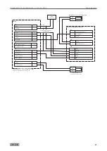
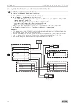
Page 26: ...A1 to day night switchover set Signals Input signals Bolt contact type to electric strike set Door parameters Electric strike type to motor lock à à Voltage supply of the MST 210 from separate power supply NT 19 2 24 or from the DCU2 control EMD Invers à à If the door opening output of the EMD Invers is adjusted to motor lock the door is only held in the closing position via the IQ lock EL no long...

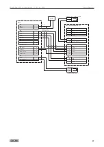
Page 27: ... Door handle 17 16 X2 24 V DC Door contact IN 2 6 X5 COM Release NO Release 12 13 COM NO Push button Access control Key switch COM NO Door contact AUT Automatic 8 NA Night 24 V DC 6 2 24 V DC Mechanical contact 2 20 KB DCU2 ControlSlimdrive EMD Active Leaf DO Permanently open 9 PS TOEA 31 TOEB RM 32 33 PA1A PA1B 55 56 PA1 24 V DC 2 TOE 24 V DC 2 GND 1 Voltage from power supply or from DCU2 When th...

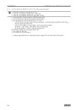
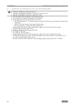
Page 28: ...ctive leaf X X Set the parameters on the control DCU2 DCU2 F DCU I à à with DPS Set a1 to 1 8 day night switchover parameter bar message to 0 2 electric strike and TO electric strike to 03 motor lock à à with ST220 Set Signals Output signals PA1 to day night switchover Set Signals Input signals Bolt contact type to electric strike Set Door parameters Electric strike type to motor lock The followin...

Page 29: ...RM 32 33 PA1A PA1B 55 56 PA1 24 V DC 2 TOE 24 V DC 2 GND 1 GN YE 24 V DC Supply CAN H GEZE Bus CAN L GEZE Bus RS485 A RS485 B 3 46 45 42 41 Locking device Locking device Door locked 24 V DC Door closed 24 V DC 5 6 14 2 15 2 Input 1 Short term release Input 2 Short term release Input 3 Fire alarm system 9 52 53 24 V DC GND Indirect Activation Indirect Activation 2 1 7 8 24 V DC Lock key switch shor...

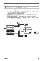
Page 30: ...n the control unit DCU5 à à with DPS Set parameter 21 bar message to 0 2 electric strike and TO 2 0 electric strike type to 0 3 motor lock à à with ST220 Set Input signals Bar message to electric strike Set Door parameters Electric strike type to motor lock à à Voltage supply of the MST 210 from separate power supply NT 19 2 24 or from the DCU 5 control à à The GND of DCU5 terminal TOE no 1 must b...

Page 31: ... button Access control Key switch 24 V DC in 3 24 V DC Release 24 V DC Day Night 2 5 2 4 COM Cylinder contact NO Cylinder contact 24 25 X6 X8 MST 210 24V DC NT 19 2 24 RD GND in 1 X7 BK RD COM Door handle NO Door handle 17 16 X2 24 V DC Door contact IN 2 6 X5 COM Release NO Release 12 13 Voltage from power supply or from DCU5 DCU5 GND must be connected with MST 210 GND even when a separate power s...

Page 32: ...nd TO 2 0 electric strike type to 0 3 motor lock à à with ST220 Set Input signals Bolt signal to electric strike Set Door parameters Electric strike type to motor lock à à Voltage supply of the MST 210 from separate power supply NT 19 2 24 or from the DCU 5 control à à The GND of the DCU5 terminal TOE no 1 The following settings must be made on the TZ 320 à à Set Output 1 to BA drive à à Set Outpu...

Page 33: ...Supply CAN H GEZE Bus CAN L GEZE Bus RS485 A RS485 B 3 46 45 42 41 Locking device Locking device Door locked 24 V DC Door closed 24 V DC 5 6 14 2 15 2 Input 1 Short term release Input 2 Short term release Input 3 Fire alarm system 9 52 53 24 V DC GND Indirect Activation Indirect Activation 2 1 7 8 24 V DC Lock key switch short term release acknowledge Unlock key switch acknowledge 2 12 11 X 106 or...

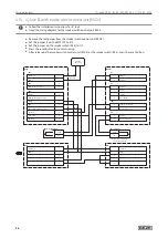
Page 34: ...t Jumper J1 of the MST 210 to 2 3 Connection via external 24 V supply voltage EMD Invers à à If the door opening output of the EMD Invers is adjusted to motor lock the door is only held in the closing position via the IQ lock EL no longer via the door drive à à The door opens through spring force in the event of manual passage after the panic bar has been pressed à à After the hold open time has e...

Page 35: ... à à The GND of DCU5 terminal TOE no 1 must be connected with the GND in the MST 210 terminal X7 no 1 even when a separate power supply is used à à The day function on the lock cannot be used with analogue programme switches DPS TPS MPS à à When the mode of operation permanently open or day is used the jumper J1 of the MST 210 must be set to 2 3 Connection via external 24 V DC supply voltage à à W...

Page 36: ...X After release by the smoke switch control unit RSZ 6 or the smoke switch RS 5 press the reset button GND in 2 24 V DC MRB Manual trigger switch 5 6 KL2 RSZ6 24 V DC in 1 KL1 HOD Hold open device 4 GND 3 24 V DC GND 7 8 AS Ceiling mounted detector NC Alarm 9 10 COM Alarm 11 NO Alarm 12 24 V DC NT 19 2 24 RD BK RD COM NO 24 V DC in 3 24 V DC Release 24 V DC Day Night 2 5 2 4 COM Smoke detector NC ...

Page 37: ...ND in 1 X7 Supply 24 V DC Release 24 V DC Day Night 2 5 2 4 X6 Mode of Operation IN COM Cylinder NO Cylinder 24 25 X8 Cyl Con Sabo OUT 24 V DC Door contact IN 2 6 X5 Door contact IN COM RSK NO RSK 20 21 X3 RSK OUT COM Door handle NO Door handle 17 16 X2 Outputs COM Release NO Release 12 13 COM Day Night NO Day Night 10 11 COM Fault Alarm NC Alarm 17 15 COM Door status NO Door status 18 19 8 9 X4 S...

Page 38: ...diagram for the hold open system FA CG 150 X X Set jumper J3 on the smoke switch control unit RSZ6 to 2 3 X X Separate the breaking point in the first relay base X X Do not separate the breaking point in the last relay base X X Set jumper J1 on the MST 210 to 2 3 X X Press the reset button for commissioning X X After activating the smoke switch control unit or the smoke switches press the reset pu...

Page 39: ...ay Night NO Day Night 10 11 COM Fault Alarm NC Fault Alarm 17 15 COM Door status NO Door status 18 19 8 9 X4 Smoke detector IN COM Cylinder NO Cylinder 24 25 X10 Deckelüberw OUT Cable IQ lock RD BK GY PK RD BU VT WH BN GN YE GY PK BU X9 X1 Lock 27 28 2 31 32 33 34 35 36 37 38 39 TPF 27 X12 28 X11 27 28 X13 1 2 J1 3 4 COM NO Reset COM NO TK NT 24V DC 1 2 J1 1 2 J2 1 2 J3 3 RSZ6 7 8 6 5 11 12 10 9 2...

Page 40: ...to the day night input of the MST 210 Output 1 must be configured to BA drive for this function Option 2 As an option the output cylinder contact terminals 24 25 of the MST 210 can be connected to a configurable input of the TZ 320 terminals 2 and 52 or 53 Function When the cylinder is actuated by the key a short term release is triggered at the door control unit If only a short term release is de...

Page 41: ...EZE Bus CAN L GEZE Bus RS485 A RS485 B 3 46 45 42 41 Locking device Locking device Door locked 24 V DC Door closed 24 V DC 5 6 14 2 15 2 Input 1 Short term Release Input 2 Cylinder Contact Input 3 Door Handle 9 52 53 24 V DC GND Indirect activation Indirect activation 2 1 7 8 24 V DC Lock key switch short term release acknowledge Unlock key switch acknowledge 2 12 11 X 106 orange Terminal strip X ...

Page 42: ...2 Wiring diagrams 6 14 IQ lock EL with K600 and activation X X Follow the installation instructions for IQ lock X X Heed the wiring diagram of the retractable arm drive RWA K600 X X Heed the wiring diagrams of the control panels E260 N THZ MBZ 300 ...

Page 43: ...V DC in 3 Control panel Control panel 10 11 X3 MST 212 GND in 1 X2 24V DC NT 19 2 24 RD BK RD BU BN N L1 6 A BU BN GND 24 V DC 1 2 X4 Activation Alarm output 5 80 COM Alarm NO Alarm 90 91 X5 NC Alarm 92 COM NO Push button access control key switch COM NO Door contact IN When the door is closed the contact is closed Motor CLOSED Open 3 COM Electric strike NO Electric strike 2 1 K600 Motor open CLOS...

Page 44: ...ivation X X Follow the installation instructions for IQ lock X X Heed the wiring diagram of the retractable arm drive RWA K600 X X Heed the wiring diagrams of the control panels E260 N THZ MBZ 300 X X Heed the wiring diagram for GEZE SecuLogic RWS TZ 320 X X On the TZ 320 set output 1 to TOE working current ...

Page 45: ...is closed the contact is closed COM NO Push button access control key switch GN YE 24 V DC Supply CAN H GEZE Bus CAN L GEZE Bus RS485 A RS485 B 3 46 45 42 41 Locking device Locking device Door locked 24 V DC Door closed 24 V DC 5 6 14 2 15 2 Input 1 Short term release Input 2 Short term release Input 3 Fire alarm system 9 52 53 24 V DC GND Indirect Activation Indirect Activation 2 1 7 8 24 V DC Lo...

Page 46: ... Wiring diagrams 6 16 IQ lock AUT with K600 and activation X X Follow the installation instructions for IQ lock X X Heed the wiring diagram of the retractable arm drive RWA K600 X X Heed the wiring diagrams of the control panels E260 N THZ MBZ 300 ...

Page 47: ...ase 2 5 X6 MST 210 GND in 1 X7 24 V DC Door contact IN 2 6 X5 Motor CLOSED Open 3 COM Electric strike NO Electric strike 2 1 K600 Passive leaf Motor open CLOSED 4 Motor CLOSED Open 3 COM Electric strike NO Electric strike 2 1 K600 Active leaf Motor open CLOSED 4 COM NO Push button access control key switch COM NO Door contact When the door is closed the contact is closed GND in 24 V DC in 24 V DC ...

Page 48: ...mechanical installation instructions for IQ lock X X Heed the wiring diagram of the retractable arm drive RWA K600 X X Heed the wiring diagrams of the control panels E260 N THZ MBZ 300 X X Heed the wiring diagram for GEZE SecuLogic RWS TZ 320 The following settings must be made on the TZ 320 X X Set Output 1 to TOE working current ...

Page 49: ...e Tür verriegelt 24 V DC Door locked 24 V DC 5 6 14 2 15 2 Input 1 Short term release Input 1 Short term release Input 3 Fire alarm system 9 52 53 24 V DC GND Indirect activation Indirect activation 2 1 7 8 24 V DC Lock key switch short term release acknowledge Unlock key switch acknowledge 2 12 11 X 106 orange Terminal strip X 107 green Terminal strip X 105 black Terminal strip TZ 320 24V DC NT 1...

Page 50: ...à Set Signals Input signals Bolt contact type to electric strike à à Set Door parameters Electric strike type to motor lock Voltage supply of the MST 210 from separate power supply NT 19 2 24 or from the DCU2 control Voltage supply of the rod drive IQ AUT from separate 24 V DC 1 5 A power supply EMD Invers à à If the door opening output of the EMD Invers is configured to motor damage the door is o...

Page 51: ...KB AUT Automatic 8 NA Night 24 V DC 6 2 DO Permanently open 9 PS 24V DC 2 PA1A PA1B 55 56 GND 1 PA1 PA2 PA2 57 24V DC 2 PA1A PA1B 55 56 GND 1 PA1 PA2 PA2 57 COM NO Door contact When the door is closed the contact is closed COM NO Push button access control key switch GND in 24 V DC in 24 V DC Release 1 3 2 5 X1 IQ AUT 20 21 22 Output 1 locked COM Unlocked 42 41 GEZE BUS BU RD BN WH Plug in drip lo...

Page 52: ...PS à à Set parameter rr 21 bar message to 02 electric strike and to 20 electric strike type to 03 motor lock X X With ST220 à à Set Input signals Bar message to electric strike à à Set Door parameters Electric strike type to motor lock Voltage supply of the MST 210 from separate power supply NT 19 2 24 or from the DCU5 control The GND of DCU5 terminal TOE no 1 must be connected with the GND of the...

Page 53: ...M Unlocked 42 41 GEZE BUS BU RD BN WH Plug in drip loop 8 pole GR PK YE GN X5 24 V DC NT COM NO Door contact When the door is closed the contact is closed RS 485 B 41 RS 485 A 24V DC 42 2 SCR 43 RS 485 GND 1 DCU2 Control Slimdrive EMD passive leaf 24 V DC 2 TOEA TOEB 31 32 GND 1 TOE RM 33 24 V DC Mechanical contact 2 20 KB AUT Automatic 8 NA Night 24 V DC 6 2 DO Permanently open 9 PS RS 485 B 41 R...

Page 54: ...220 Set Door parameters Electric strike type to Motor lock Voltage supply à à Take the voltage supply MST 210 from a separate power supply or from the DCU8xx control à à Take the voltage supply rod drive IQ AUT from a separate power supply Abbreviation in illustration on page Component BGS Opposite hinge side BS Hinge side DPS Display programme switch IQ AUT Rod drive IQ lock EL DL Self locking mo...

Page 55: ...ock AUT EL EL DL EM EM DL C C DL M M DL 55 Wiring diagrams IQ lock EL DL KÜ Powerturn IS KÜ Powerturn IQ AUT KÜ KÜ 230 V 50Hz DPS SCT TK Radar BGS Radar BS VT NT MST 210 1 1 2 2 10 10 10 10 10 3 9 9 9 9 4 2 ...

Page 56: ...IQ lock AUT EL EL DL EM EM DL C C DL M M DL 56 Wiring diagrams ...

Page 57: ...rce must be used for unlocking X X Make sure that the drive rod is not blocked Wh_UL2_ON Bar_L_ON The Hall sensor at the locked position of the drive rod is active in the unlocked state This fault is only triggered in the unlocked state à à Attempted manipulation Some has tried to generate a locked signal à à The bar lock Hall sensor is defective X X Check whether the door has been manipulated X X...

Page 58: ...t the control X X Reset the activation and start activation of the lock again fault message will go out if successful Power supply cable defective Lock is not being supplied with 24 V DC X X Check continuity and replace the power supply cable of the lock if necessary Control is not being supplied with 24 V DC In the event of attempted manipulation the bolt of the auxiliary latch is closed and can ...

Page 59: ...actuation of the nightlatch function using the key Door handle is jammed in actuated position or Handle return spring is broken The door handle does not return to its initial position after actuation and there is no locking signal given X X Loosen the screws lubricate the handle guide correct fastening or X X Replace the lock Auxiliary latch is not actuated Lock does not lock when the door is clos...

Page 60: ...lock when the door is closed X X Check the clearance of the door leaf Bolt shoots out again immediately after the door has been opened Door handle has not been pressed down completely or Auxiliary latch is jammed in actuated position Slider is not held in permanently unlocked position door cannot close and be locked properly X X Press the handle down as far as it will go X X Check the tension free...

Page 61: ...ure and record the operating forces required to release the panic exit device emergency exit lock à à Ensure that the operating forces have not changed substantially in comparison to the operating forces recorded during initial commissioning à à Ensure that bolt heads or keepers are not blocked or clogged up à à Ensure that the panic exit device has been lubricated according to the manufacturer s ...

Page 62: ...ease ability passed 80 N without load 200 N with load Permanent functionality with regard to release ability in terms of ageing and loss of quality of doors on escape routes Passed 200 000 cycles 80 N Usage category Permanent function Weight of door Fire smoke protection Safety Corrosion behaviour Protection against burglary Projection of the sliding fitting system Type of actuation Application ar...

Page 63: ...0 N without load 200 N with load Permanent functionality with regard to release ability in terms of ageing and loss of quality of doors on escape routes Passed 200 000 cycles Usage category Permanent function Weight of door Fire smoke protection Safety Corrosion behaviour Protection against burglary Projection of the sliding fitting system Type of actuation Application area 3 7 7 B 1 3 4 2 A A B C...

Page 64: ...14846 2008 Usage category Permanent function and latch load Door weight and closing force Suitability for use on fire control smoke protection doors Safety Corrosion resistance temperature and humidity Protective effect and drilling resistance Protective effect with regard to electrical function Protective effect with regard to electrical manipulation 3 X 8 E 0 M 5 0 3 ...

Page 65: ...IQ lock AUT EL EL DL EM EM DL C C DL M M DL 65 Annex 9 2 Certificate to state the constancy of performance in accordance with EN 1125 ...

Page 66: ...IQ lock AUT EL EL DL EM EM DL C C DL M M DL 66 Annex ...

Page 67: ...IQ lock AUT EL EL DL EM EM DL C C DL M M DL 67 Annex 9 3 Certificate to state the constancy of performance in accordance with EN 179 ...

Page 68: ...IQ lock AUT EL EL DL EM EM DL C C DL M M DL 68 Annex ...

Page 69: ...IQ lock AUT EL EL DL EM EM DL C C DL M M DL 69 Annex 9 4 Certificate recognising components and systems in accordance with VdS ...

Page 70: ...IQ lock AUT EL EL DL EM EM DL C C DL M M DL 70 Annex ...

Page 71: ...IQ lock AUT EL EL DL EM EM DL C C DL M M DL 71 Annex ...

Page 72: ...ance fr geze com www geze fr Hungary GEZE Hungary Kft E Mail office hungary geze com www geze hu Iberia GEZE Iberia S R L E Mail info es geze com www geze es India GEZE India Private Ltd E Mail office india geze com www geze in Italy GEZE Italia S r l E Mail italia it geze com www geze it GEZE Engineering Roma S r l E Mail italia it geze com www geze it Korea GEZE Korea Ltd E Mail info kr geze com...

Reviews: