


IQ lock AUT, EL / EL DL, EM / EM DL, C / C DL, M / M DL
15
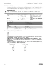
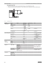
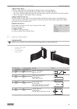
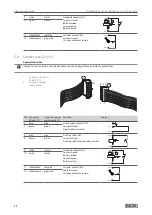
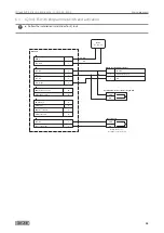
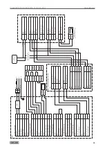
Electrical connection
Connector IQ lock EL
6 12
1 7
6 12
7
1
PIN
1
2
3
4
5
6
7
8
9
10
11
12
Connector IQ lock EL /
IQ lock EL DL (1)
black
red
blue
orange
grey
yellow
green
brown
white
violet
white/black
white/brown
Connector power supply
cable (2)
black
red
blue
pink
grey
yellow
green
brown
white
violet
red/blue
grey/pink
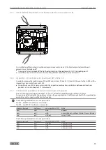
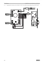
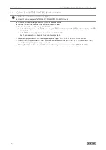
5.1.3 Low-pass filter (TPF)
New from mid-2014.
The low-pass filter (TPF) ensures improved activation of the motor lock IQ lock EL / IQ lock EL DL. Here, the
motor control cable (red and black cables) are not connected directly to the motor lock control MST 210, they are
connected with terminal X12 of the additional PCB TPF.
The TPF has been optimised for the new motor drive unit in the lock and for the new software (see chapter 5.1.4
and chapter 5.1.6). Taking the conditions listed in chapter 5.1.7 into account, the TPF can also be used for locks
with an older building design.
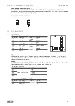
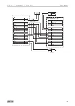
Insert TPF board on MST 210
23
2
2
X10
24
25
X8
26
X5
89
X4
20
2
1
X3
5
2
X6
4
2
3
1
X7
121
3
X2
10
11
16
17
14
15
18
19
23
1
X1
27
28
34
35
32
33
38
39
36
37
JP1
JP2
F1
F2
X9
X11
LED1
ON
1 2 3 4
LED6
LED5
LED4
LED3
LED2
1
2
X13
X12
X11
Tiefpassfilter X11
Tiefpassfilter X11
X
Insert the TPF board (1) onto slot X9 of the motor lock control MST 210 (2).
Summary of Contents for IQ lock AUT
Page 56: ...IQ lock AUT EL EL DL EM EM DL C C DL M M DL 56 Wiring diagrams ...
Page 66: ...IQ lock AUT EL EL DL EM EM DL C C DL M M DL 66 Annex ...
Page 68: ...IQ lock AUT EL EL DL EM EM DL C C DL M M DL 68 Annex ...
Page 70: ...IQ lock AUT EL EL DL EM EM DL C C DL M M DL 70 Annex ...
Page 71: ...IQ lock AUT EL EL DL EM EM DL C C DL M M DL 71 Annex ...


