17
Electrical Connection
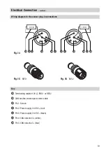
1. Unscrew screws
8
and remove cover
0
.
Fig. 13
2. Loosen nut
e
with 19 mm spanner. Do not remove it!
Fig. 14
The electrode terminal box can now be turned t/– 180°.
3. Turn electrode terminal box into desired position (+/– 180°).
4. Tighten nut
e
with a torque of
25 Nm
.
5. Set node ID (see
“Basic Settings”, “Configuring level electrode”
).
6. Re-attach cover
0
and fix it with screws
8
.
Control cable
UNITRONIC
®
is a registered trademark of LAPP Kabelwerke GmbH, Stuttgart.
Aligning terminal box
Note
n
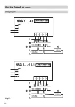
Wire the control cable according to the wiring diagram with connector socket and plug.
NRS, NRR, LRR, TRS, URB 1
To wire the equipment screened multi-core twisted-pair control cable
must
be used for the bus line,
e. g. UNITRONIC
®
BUS CAN 2 x 2 x ... mm
2
or RE-2YCYV-fl 2 x 2 x ... mm
2
.
Control cable assemblies (2 x 2 x 0.32 mm² cable with plug and socket) of various lengths are available
as add-on equipment.
NRG, LRG, EF, URZ, TRV, URB 2
The equipment is fitted with sensor plug-in connectors (5 poles, A-coded). For connecting the bus
devices control cable assemblies (with plug and socket) of various lengths are available as add-on
equipment.
Note that the recommended control cables are not UV-resistant and must be protected by a
UV-resistant plastic tube or cable duct if the equipment is installed outdoors (except for URB 2).
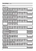
The baud rate (data transfer rate) dictates the cable length and size between the bus nodes. The total
power consumption must also be taken into consideration when selecting the conductor size. The
total power consumption is obtained from the number of bus nodes. If the cable length between the
steam boiler and the control cabinet exceeds 15 m, we recommend that you fit a branching box that is
resistant to electromagnetic interference (stock code 1501214) and use a control cable with a larger
conductor size for the distance to the control cabinet.
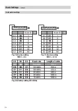
S 8
S 9
S 10
Baud rate
Cable length
Number of pairs
and conductor size [mm
2
]
OFF
ON
OFF
250 kBit/s
125 m
2 x 2 x 0.34
Factory setting
ON
ON
OFF
125 kBit/s
250 m
2 x 2 x 0.5
OFF
OFF
ON
100 kBit/s
335 m
2 x 2 x 0.75
ON
OFF
ON
50 kBit/s
500 m
on request, depending on
bus configuration
OFF
ON
ON
20 kBit/s
1000 m
ON
ON
ON
10 kBit/s
1000 m
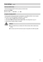
Set baud rate via code switch
b
. Make sure that all bus nodes feature the same settings.
Summary of Contents for NRG 16-41
Page 27: ...27 For your Notes ...


