background image

28

810743-04/04-2017cm (808720-03) · GESTRA AG · Bremen · Printed in Germany

GESTRA AG

Münchener Straße 77 
28215 Bremen
Germany
Telefon  +49 421 3503-0  
Telefax   +49 421 3503-393
E-mail   [email protected]
Web www.gestra.de

Agencies all over the world: 


www.gestra.de

Summary of Contents for NRG 16-41

Page 1: ...1 E N English Original Installation Instructions 810743 04 Level Electrode NRG 16 41 NRG 16 41 1 NRG 17 41 NRG 17 41 1 NRG 19 41 NRG 19 41 1 ...

Page 2: ...1 1 NRG 17 41 41 1 NRG 19 41 41 1 step 1 14 NRG 16 41 41 1 NRG 17 41 41 1 NRG 19 41 41 1 step 2 14 Attention 14 Note 14 Tools 14 Examples of installation NRG 16 41 1 NRG 17 41 1 NRG 19 41 1 15 Key 16 Installation NRG 16 41 41 1 NRG 17 41 41 1 NRG 19 41 41 1 7 Name plate marking 8 Dimensions NRG 16 41 41 1 NRG 17 41 41 1 9 Dimensions NRG 19 41 41 1 10 Technical Data NRG 16 41 41 1 NRG 17 41 41 1 NR...

Page 3: ...agram 20 Attention 20 Note 21 Tools 21 Contents continued Page Malfunctions Fault finding list for troubleshooting 26 Operation High water level limiter Max alarm 25 Note 25 Commissioning Procedure Check wiring 25 Apply mains voltage 25 Basic Settings CAN bus 21 Node ID 22 Factory set default values 23 Assigning changing node ID 23 Attention 23 Code switch settings 24 ...

Page 4: ...s hot steam can escape through the lateral vent hole on the electrode body This presents the risk of severe scalding Do not stay near the electrode during operation Safety note The equipment must only be installed and commissioned by qualified staff Maintenance and service work must only be performed by adequately trained persons who have a recognized level of competence Attention The name plate i...

Page 5: ...G 19 41 1 1 S S joint ring D 27x32 mm to DIN 7603 made of 1 4301 bright annealed 1 Terminating resistor 120 Ω 1 Installation manual Description The level electrode operation is based on the conductive measuring principle The NRG 1 41 and NRG 1 41 1 are designed for signalling the max liquid level in electrically conductive liquids n One liquid level with one switchpoint The NRG 1 41 is to be used ...

Page 6: ...ivity of the liquid is used to signal the liquid level Some liquids are conductive which means that they allow an electric current to flow through them For the safe functioning of this device a minimum conductivity of the liquid to be measured is required The conductivity measurement method can detect two conditions electrode rod submerged or exposed meaning switchpoint reached or exceeded or not ...

Page 7: ...lation PEEK Lengths supplied 500 mm 1000 mm 1500 mm Sensitivity of response 0 5 µS cm at 25 C Supply voltage 18 36 V DC coming from NRS 1 41 NRS 1 40 1 NRS 1 40 2 Current consumption 35 mA Fuse Electronic thermal fuse Tmax 85 C Hysteresis 2 K Electrode voltage 2 Vss Data exchange CAN bus to DIN ISO 11898 CANopen Protocol Indicators and adjustors One 10 pole code switch for setting node ID and baud...

Page 8: ...ar 1450psi 311 C 592 F Node ID __ __ __ 0525 GESTRA AG Münchener Str 77 D 28215 Bremen TÜV SWB SHWS STW STB xx 413 0 5 µS cm Betriebsanleitung beachten See installation instructions Hier öffnen Open here Ouvrir ici Voir instructions de montage 18 36 V DC Tamb 70 C 158 F IN OUT CAN Bus PN 63 PN 160 PN 40 Pmax Tmax NRG 17 41 NRG 19 41 NRG 16 41 G 3 4 1 4571 IP65 60 bar 870psi 260 C 500 F 32 bar 464p...

Page 9: ...9 GESTRA Steam Systems GESTRA NRG 1 41 1 MAX Fig 2 EN ISO 228 1 1500 1000 1500 140 337 5 185 Technical Data continued Dimensions NRG 16 41 41 1 NRG 17 41 41 1 175 85 30 ...

Page 10: ...10 GESTRA Steam Systems GESTRA NRG 1 41 1 MAX Fig 3 EN ISO 228 1 1500 1000 1500 175 140 419 30 185 120 Technical Data continued Dimensions NRG 19 41 41 1 ...

Page 11: ...11 Fig 6 Fig 4 Fig 5 Fig 7 N 8 N 10 0 5 EN ISO 228 1 33 Design NRG 16 41 41 1 NRG 17 41 41 1 NRG 19 41 19 41 1 5 f 6 7 1 2 3 4 ...

Page 12: ...12 K H 1 1 2 2 3 3 1 2 3 4 5 LW HW 1 2 3 5 6 7 4 8 910 ON P R O D U C T D E S I G N A W A R D MAX Functional Elements Fig 8 Fig 9 NRG 16 41 41 1 NRG 17 41 41 1 NRG 19 41 19 41 1 9 0 9 8 a e d b c ...

Page 13: ...9 M 12 sensor plug 5 poles A coded M 12 sensor socket 5 poles A coded 0 Cover a LED green Program running LED red CAN bus communication b 10 pole code selector for setting node ID and baud rate c Terminal strip d PE connection e Plug f Thermal insulation provided on site d 20 mm outside of thermal insulation of steam generating unit Design Functional Elements continued Key ...

Page 14: ...1 Slide spring 3 along electrode tip 4 so that its end completely enters into small bore 2 Note n For the approval of the boiler standpipe the relevant regulations must be considered n Refer to page 15 for three typical installation examples Tools n Open end spanner A F 17 mm n Open end spanner A F 41 mm n Hacksaw n Flat file medium cut NRG 16 41 41 1 NRG 17 41 41 1 NRG 19 41 19 41 1 step 2 1 Chec...

Page 15: ...DN 20 24 5 24 5 20 20 Fig 10 Fig 12 1 20 3000 DN 20 20 90 10 Installation continued Examples of installation NRG 16 41 1 NRG 17 41 1 NRG 19 41 1 i g h k m n 9 0 Centre distance g j o k 1 20 20 DN 50 20 90 g h i n k l j o p j j ...

Page 16: ...ns must be considered i Vent hole Provide vent hole as close to the boiler wall as possible j High water level HW k Electrode rod d 8 mm l Protection tube DN 80 m Protection tube DN 100 n Electrode distance 14 mm o Low water level p Reducer DIN 2616 2 K 88 9 x 3 2 42 4 x 2 6 W q Reducer DIN 2616 2 K 114 3 x 3 6 48 3 x 2 9 W Installation continued Key ...

Page 17: ...semblies with plug and socket of various lengths are available as add on equipment Note that the recommended control cables are not UV resistant and must be protected by a UV resistant plastic tube or cable duct if the equipment is installed outdoors except for URB 2 The baud rate data transfer rate dictates the cable length and size between the bus nodes The total power consumption must also be t...

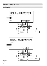
Page 18: ...18 NRG 1 41 1 HW 1 2 3 S CL CH 18V 36V DC CAN Bus 120 Ω 1 2 3 4 5 1 ON 2 3 4 5 6 7 8 9 0 Electrical Connection continued Wiring diagram r s Fig 13 r s ...

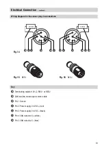
Page 19: ...nnection continued Fig 15 RES 1 Fig 16 RES 2 r Terminating resistor 120 Ω RES 1 or RES 2 s CAN bus line twisted pair control cable t Pin 1 Screen u Pin 2 Power supply 24 V DC red v Pin 3 Power supply 24 V DC black w Pin 4 CAN data line CH white x Pin 5 CAN data line CL blue Key x x 120 Ω 120 Ω ...

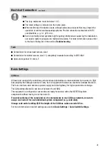
Page 20: ...the screen is separated from the central earthing point CEP n To protect the switching contacts fuse circuit with T 2 5 A or according to TRD regulations 1 0 A for 72 h operation n If two or more system components are connected in a CAN bus system provide the first and the last device with a terminating resistor of 120 Ω Fig 15 Fig 16 n Note that in a CAN bus network only one water level limiting ...

Page 21: ...ult finding list in the section Troubleshooting CAN bus All level and conductivity controllers and associated electrodes are interconnected by means of a CAN bus adopting the CANopen protocol Every item of equipment features an electronic address Node ID The four core bus cable serves as power supply and data highway for high speed data exchange The CAN address Node ID can be set between 1 and 123...

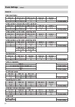
Page 22: ...RV 5 40 2 Limiter 3 Limiter 4 X X 1 X 2 X 3 X 4 6 7 8 9 10 Factory setting TRS 5 40 1 TRS 5 40 2 X 1 90 X 2 90 97 98 High level alarm NRS 1 41 NRG 16 41 Reserved Reserved Reserved X X 1 X 2 X 3 X 4 6 7 8 9 10 Factory setting Further components SRL 40 X sensor level limiter hi alarm 2 Factory setting ORT 6 98 Factory setting On off level control Reserved NRS 1 42 NRG 16 42 X 1 X X 1 19 20 21 Factor...

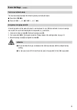
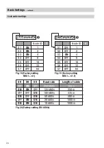
Page 23: ...actory setting n Do not use a node ID for more than one piece of equipment in the CAN bus system Assigning changing node ID If several systems of the same kind are to communicate in one CAN bus network be sure to assign one node ID for each individual system component e g controller 1 Undo and remove screws 8 Remove housing cover 0 2 Set code switch b to the required position Please observe the se...

Page 24: ...D S1 1 OFF S2 2 ON S3 4 OFF S4 8 OFF S5 16 OFF S6 32 OFF S7 64 ON Node ID S1 1 ON S2 2 ON S3 4 OFF S4 8 OFF S5 16 OFF S6 32 OFF S7 64 7 4 Baud rate S8 S9 S0 250 kBit s Length of cable 125 m OFF ON OFF OFF 125 kBit s ON ON 250 m ON 100 kBit s OFF OFF 335 m ON 50 kBit s OFF ON 500 m ON 20 kBit s ON OFF 1000 m ON 10 kBit s ON ON 1000 m b b 1 ON 2 3 4 5 6 7 8 9 0 ...

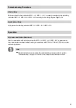
Page 25: ...ram Fig 13 14 Check wiring Apply mains voltage Operation Used in combination with switching controller NRS 1 41 NRS 1 40 1 NRS 1 40 2 in pressurized hot water plants and steam boilers working in accordance with TRD 401 TRD 602 TRD 604 or other national regulations High water level limiter Max alarm Note n Should malfunctions occur during the commissioning procedure refer to section Troubleshooting...

Page 26: ... level electrode with hemp or PTFE tape Fault The vent hole in the protection tube does not exist is obstructed or flooded Remedy Check protection tube and if necessary provide vent hole Fault The isolating valves of the external measuring pot optional item are closed Remedy Open isolating valves Equipment fails to work Indication of a malfunction Fault In spite of correct wiring and commissioning...

Page 27: ...27 For your Notes ...
Page 28: ...8720 03 GESTRA AG Bremen Printed in Germany GESTRA AG Münchener Straße 77 28215 Bremen Germany Telefon 49 421 3503 0 Telefax 49 421 3503 393 E mail info de gestra com Web www gestra de Agencies all over the world www gestra de ...

Reviews: