21
Electrical Connection
– continued –
Tools
n
Screwdriver for cross head screws, size 1
n
Screwdriver for slotted screws, size 2.5, completely insulated according to VDE 0680
n
Open-end spanner 19 mm A. F.
Note
n
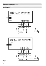
The loop resistance must be below 10 Ω.
n
The rated voltage is indicated on the name plate.
n
When switching off inductive loads, voltage spikes are produced that may impair the
operation of control and measuring systems. Provide connected contactors with RC
combinations, e. g. 0.1 µF/100 Ω.
n
Even in correctly wired systems high frequency interference caused by the installation
can lead to system outages and malfunction alarms. For more information please refer
to the fault-finding list in the section
Troubleshooting
.
CAN bus
All level and conductivity controllers and associated electrodes are interconnected by means of a CAN
bus adopting the CANopen protocol. Every item of equipment features an electronic address (Node ID).
The four-core bus cable serves as power supply and data highway for high-speed data exchange.
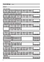
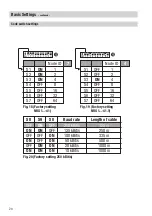
The CAN address (Node ID) can be set between
1
and
123
.
The equipment is configured at our works and ready for service with other GESTRA system
components without having to set the node ID.
If several systems of the same kind are to communicate in one CAN bus network, be sure to
assign one node ID for each individual system component (e. g. controller).
Change code switch setting
b
if the length of the CAN bus cable exceeds 125 m.
For more information on switch settings see section
Basic Settings / Code Switch Settings.
Basic Settings
Summary of Contents for NRG 16-41
Page 27: ...27 For your Notes ...


