Gerber Technology GPS-2000 Manual Download Page 2

Function

Description

Annotation

Add

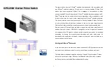
1.Set your Z-Wave controller into 

inclusion mode by following the 

instructions provided by the 

controller manufacturer. 

2.The green LED   will light

 on when every pressing and
 light off when every releasing.
 User should check LED 

 whether it accepted the
 pressing or not.
  Surround Blue LED light will
 flash one time when enter
 include mode.
3.If included successfully,
 Surround Blue LED light will
 flash one time again.   

2. Press the middle button (button 

)

three times within 2 seconds

    intervals and device will enter 

inclusion mode.

3. Node ID is included.

Remove

1.Put your Z-Wave controller into 

exclusion mode by following the 

instructions provided by the 

Controller manufacturer.

2.The green LED   will light

 on when every pressing and
 light off when every releasing.
 User should check LED 

 whether it accepted the
 pressing or not.
 Surround Blue LED light will
 flash one time when enter
 exclude mode.

2. Press the middle button (button 

)

three times within 2 seconds will 

enter exclusion mode.

3. Node ID will get excluded.

Reset

1.Press the middle button (button 

)  Use this procedure only in 

four times and hold the button on 

the 4th time for about 3~10 

seconds, then release button.

the event that the primary 
controller looses connection.

The green LED   will light on

when every pressing and light
off when every releasing. User
should check LED   whether

it accepted the pressing or not.

Surround Blue LED will light on
at the 4th pressing and 5
 seconds later light off.
If reset successfully, Surround
Blue LED light will flash one
time. 

2.IDs will get excluded and all 

settings will be reset.

SmartStart

1. SmartStart enabled products can be 

added into a Z-Wave network by 

scanning the Z-Wave QR Code on 

the product, with a controller 

providing SmartStart inclusion. No 

further action is required and the 

SmartStart product will be added 

automatically to the closest network 

within 10 minutes of being switched 

on in the network vicinity.

2

Summary of Contents for GPS-2000

Page 1: ...enu allows remote operation of the unit and connected load Remote control of Dimmer Relay modules are possible with other manufacturer s wireless Controller as well GPS 2000 is designed to act as a re...

Page 2: ...light will flash one time when enter exclude mode 2 Press the middle button button three times within 2 seconds will enter exclusion mode 3 Node ID will get excluded Reset 1 Press the middle button bu...

Page 3: ...ve Controller LED light Indication To distinguish which module is in use you can view the LED light for identification State Type LED Indication Relay module The LED or will change color from blue to...

Page 4: ...buttons are smart buttons which can send central scene command to group 1 and Basic_Set command to group 3 5 6 or 8 Programming 1 Controlling relay module by Z Wave command The relay module will resp...

Page 5: ...t 0x00 Command Class COMMAND_CLASS_BASIC Command BASIC_REPORT Value 0x00 or 0xFF 2 Controlling dimmer module by Z Wave command The dimmer will respond to BASIC_SET and MULTILEVEL_SWITCH_SET commands t...

Page 6: ...dpoint 0x08 or 0x03 Command Class COMMAND_CLASS_BASIC Command BASIC_GET Basic Report Command Command Class COMMAND CLASS MULTI CHANNEL MULTI CHANNEL CMD ENCAP Source endpoint 0x08 or 0x03 Destination...

Page 7: ...oup7 which correspond to relay modules 1 and 2 support COMMAND_CLASS_SWITCH_BINARY The relay modules 1 and 2 correspond to endpoints 1 and 6 The device type of endpoints 1 and 6 is POWER SWITCH BINARY...

Page 8: ...2 Basic_Set Group2 Switch_Binary_ Set Group2 Basic_Set Group2 Switch_Multilev el_Set Multi Channel Command Class information of endpoints Root Device Device type POWER_SWITCH_BINARY Supported Command...

Page 9: ...NTRAL_SCENE COMMAND_CLASS_ASSOCIATION COMMAND_CLASS_ASSOCIATION_GRP_INFO COMMAND_CLASS_MULTI_CHANNEL_ASSOCIATION COMMAND_CLASS_SUPERVISION COMMAND_CLASS_SECURITY COMMAND_CLASS_SECURITY_2 Controlled Co...

Page 10: ...MULTI_CHANNEL_ASSOCIATION COMMAND_CLASS_SUPERVISION COMMAND_CLASS_SECURITY COMMAND_CLASS_SECURITY_2 Controlled Command Classes COMMAND_CLASS_BASIC Description When one short press on smart button it w...

Page 11: ...OMMAND_CLASS_SECURITY COMMAND_CLASS_SECURITY_2 Controlled Command Classes COMMAND_CLASS_SWITCH_MULTILEVEL Description When the level of dimmer module 2 is changed and achieved the desired level it wil...

Page 12: ...mum 2 Nodes 3 1 Pressing button to switch On Off Relay Button correspond to relay1 and button correspond to relay2 When the relay is off shortly pressing the assigned button will turn it on and send B...

Page 13: ...se button after a long pressing Command Class COMMAND CLASS MULTI CHANNEL MULTI CHANNEL CMD ENCAP Source endpoint 0x03 or 0x08 Destination endpoint 0x01 send to correspond grouping nodes Command Class...

Page 14: ...o improve a function if needed Command Classes The GPS 2000 supports Command Classes including Command Class Version Required Security Class Association 2 Highest granted Security Class Association Gr...

Page 15: ...Operating Temperature 0 C 40 C Frequency Range 868 4MHz 869 85MHz EU GPS 2000 1 908 4MHz 916 0MHz US GPS 2000 2 922 927MHz Taiwan Japan GPS 2000 3 916MHz Israel GPS 2000 7 Specifications are subject t...

Page 16: ...user is encouraged to try to cor rect the interference by one of the following measures Reorient or relocate the receiving antenna Increase the separation between the equipment and receiver Connect th...

Reviews: