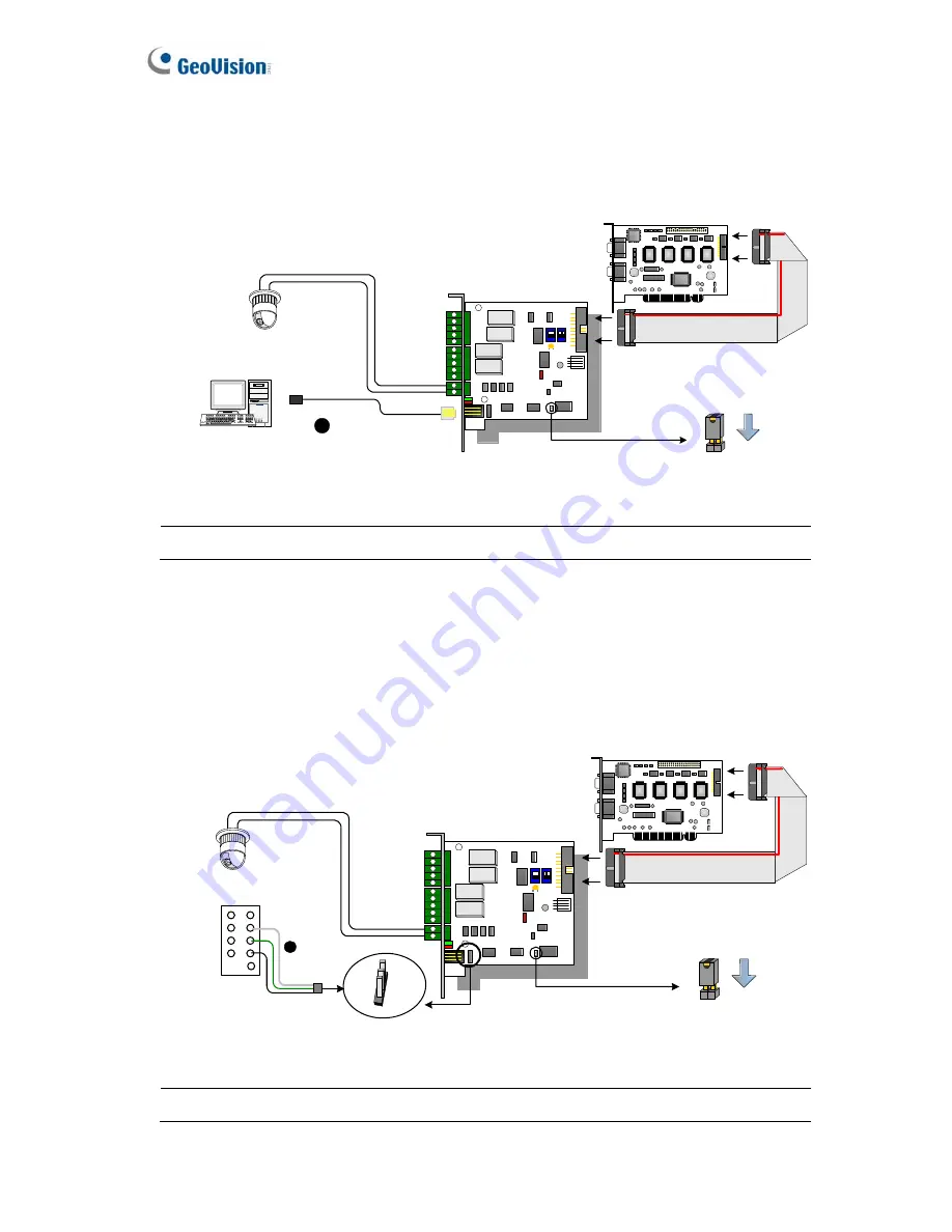
2. You can connect a RJ-11 to USB Cable to the PC's USB Port when a RS-485 device
is connected.
(Allowed for AC/DC Output Voltage)
RJ-11 to USB Cable
4
Connects to PC's USB Port
1
ON
1
2
ON
1
ON
With 2-Pin Header
PTZ Dome
RS-485+
RS-485-
GV Video Capture Card
Figure 2-17
Note:
It is required to install the USB driver. For details, see
2.23 Installing USB Driver.
3. You can connect a 3-Pin Internal USB Cable to the USB Connectors on the PC's
Motherboard when a RS-485 device is connected.
(Allowed for AC/DC Output
Voltage)
3-Pin Internal USB
Cable
Connects to the USB
Connectors on the PC 's
motherboard
DM
DP
GND
(white)
(green)
(black)
1
ON
1
2
ON
1
ON
With 2-Pin Header
PTZ Dome
RS-485+
RS-485-
GV Video Capture Card
5
VCC
DM (D-)
DP (D+)
GND
(white)
(green)
(black)
Figure 2-18
Note:
It is required to install the USB driver. For details, see
2.23 Installing USB Driver.
56
Summary of Contents for GV-650
Page 74: ...Hardware Accessories 2 Overview 3 B E Figure 2 28 71 ...
Page 98: ...4 1 Main System Silver Conventional 96 ...
Page 100: ...4 2 ViewLog Silver Conventional 98 ...
Page 113: ...Troubleshooting ...
Page 116: ...114 ...


