


Cube Camera
22
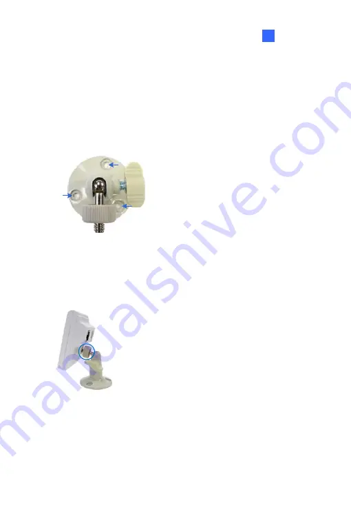
22.3 Installation
Follow the steps below to install, connect to and adjust your Cube Camera.
1.
Put the supporting rack on the desired location and make marks for
screw anchors.
2.
Drill the marks and insert the screw anchors.
3.
Secure the supporting rack onto the wall using the supplied screws.
4.
Screw the camera onto the supporting rack and fasten the indicated
screw.
5.
Connect the network and power cables to the camera. See
22.4
Connecting the Camera
in the
Quick Start Guide
.
6.
Access the live view. See
26.2 Assigning the Live View
in the
Quick
Start Guide
.
237
Summary of Contents for 88-VD37000-0020
Page 162: ... GV Software DVD Warranty Card 128 ...
Page 178: ...Pan Adjustment Tilt Adjustment Rotational Adjustment 144 ...
Page 189: ...Vandal Proof IP Dome Part II 16 16 2 Overview 1 2 3 4 5 6 8 7 9 10 12 11 13 14 155 ...
Page 199: ...Vandal Proof IP Dome Part II 16 Pan Adjustment Tilt Adjustment Rotational Adjustment 165 ...
Page 205: ...Vandal Proof IP Dome Part III 17 17 2 Overview 1 2 4 5 3 171 ...
Page 217: ...Vandal Proof IP Dome Part IV 18 18 2 Overview 13 12 10 7 8 9 11 14 183 ...
Page 236: ...19 2 Overview 1 2 3 4 5 6 13 12 10 7 8 9 14 11 202 ...
Page 254: ...Pan Adjustment Tilt Adjustment Rotational Adjustment 220 ...
Page 272: ...7 Adjust the angles of the camera based on live view and fasten the indicated screw 238 ...
Page 282: ...24 2 Overview 1 2 3 4 5 6 7 8 9 10 11 12 248 ...
Page 292: ...25 2 Overview Camera Lens 1 4 3 2 Main Body 6 7 8 9 4 5 258 ...
Page 314: ...27 The Web Interface 1 2 3 4 5 6 7 8 9 10 11 12 13 280 ...


