


Bullet Camera (Part I)
9
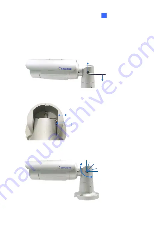
Second Shaft
You can adjust the camera body up and down by 90, 112.5, 135, 157.5 or
180 degrees by using the gears inside the camera body and the camera
base.
1.
Unscrew the tilting lock screw with the torx wrench.
Torx Wrench
Tilting Lock Screw
2.
Hold the camera body, and move the camera base to the right to
separate the camera gears.
Camera Body
Camera Gears
Move the Camera
Base to the Right
3.
Adjust the angle of camera body to 90, 112.5, 135, 157.5 or 180
degrees. Then move the camera base to the left to combine the gears.
90°
112.5°
180
°
157.5°
135 °
4.
Fasten the tilting lock screw.
75
Summary of Contents for 88-VD37000-0020
Page 162: ... GV Software DVD Warranty Card 128 ...
Page 178: ...Pan Adjustment Tilt Adjustment Rotational Adjustment 144 ...
Page 189: ...Vandal Proof IP Dome Part II 16 16 2 Overview 1 2 3 4 5 6 8 7 9 10 12 11 13 14 155 ...
Page 199: ...Vandal Proof IP Dome Part II 16 Pan Adjustment Tilt Adjustment Rotational Adjustment 165 ...
Page 205: ...Vandal Proof IP Dome Part III 17 17 2 Overview 1 2 4 5 3 171 ...
Page 217: ...Vandal Proof IP Dome Part IV 18 18 2 Overview 13 12 10 7 8 9 11 14 183 ...
Page 236: ...19 2 Overview 1 2 3 4 5 6 13 12 10 7 8 9 14 11 202 ...
Page 254: ...Pan Adjustment Tilt Adjustment Rotational Adjustment 220 ...
Page 272: ...7 Adjust the angles of the camera based on live view and fasten the indicated screw 238 ...
Page 282: ...24 2 Overview 1 2 3 4 5 6 7 8 9 10 11 12 248 ...
Page 292: ...25 2 Overview Camera Lens 1 4 3 2 Main Body 6 7 8 9 4 5 258 ...
Page 314: ...27 The Web Interface 1 2 3 4 5 6 7 8 9 10 11 12 13 280 ...


