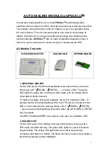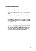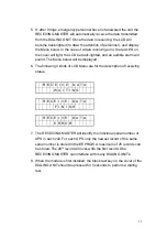
3. EEPROM Board
An 8PIN EEPROM board with DB9 connector for parameter storage is
provided. The details of the Parameter Setting procedure are shown below.
(B) LCD Screen Display
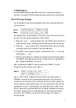
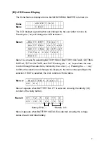
The Home Menu of the Receiving Master LCD will be activated when the
unit is powered.
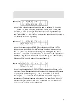
Home
Menu
A U T O C A L L
S E R V I C E
2 0 0 0 / 1 0 / 1 2
1 2 : 0 0
The display will be as shown above. The time in second row can be set by
the user. The time setting procedure is shown below:
1. Press the
↑
and
←┘
keys simultaneously. The YEAR in the second row
begins to blink slowly, indicating that the setting procedure has started.
2. Press the
←┘
key a second time. The blinking will become more rapid,
indicating that the unit is ready for the year data entry.
3. The YEAR can be changed upward or downward by the
↑
or
↓
key, and
confirmed by
←┘
key.
4. After the year setting is completed, the display will automatically shift to
the MONTH. Repeating the procedure of instructions 2-3, the MONTH,
DAY, HOUR and MINUTE can be set.
After completing the MINUTE setting, pressing the DOWN
↓
key will
change the LCD to another menu, Menu 1.
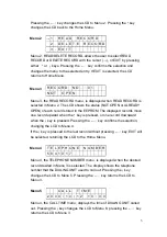
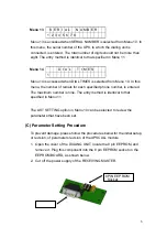
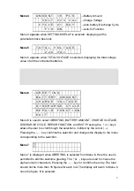
Menu 1
U P S C A L L S : 0 2
N O T O P E N : 0 1
Menu 1, UPS CALLS, indicates the total number of records stored in
EEPROM, received from an individual DIALING UNIT when abnormal
events occur. A maximum of 25 records can be stored. These records will
not be erased by cutting off the power, but only overwritten by the 26
th
and
subsequent records. For identification, the individual serial number of the
UPS is entered into each DIALING UNIT during the installation procedure.
For details, please refer to the following Menu 8 and Parameter Setting
Procedure. ‘NOT OPEN’ in the second row describes the number of
records unread.
2
Summary of Contents for Triathlon III T3UPS-13-15K
Page 18: ...1 7 Dimension Drawings 10KVA 60KVA OUTLINE DRAWING 1 13...
Page 19: ...10KVA 60KVA INTERIOR DRAWING 1 14...
Page 20: ...75KVA 160KVA OUTLINE DRAWING 1 15...
Page 21: ...75KVA 160KVA INTERIOR DRAWING 1 16...
Page 22: ...175KVA 320KVA OUTLINE DRAWING 1 17...
Page 23: ...175KVA 320KVA INTERIOR DRAWING 1 18...
Page 24: ...INTER PCB DIAGRAM 1 19...
Page 31: ...1...
Page 35: ...3 3...
Page 70: ...ONE TO TWO SERIAL REDUNDANCY 8 3...
Page 77: ...Appendices Additional Data on Options UPSCOMTM UPSCALLTM DCMANTM...
Page 80: ...3...
Page 81: ......

