14
ENGLISH
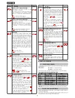
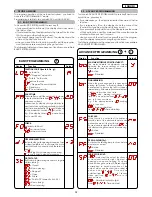
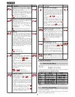
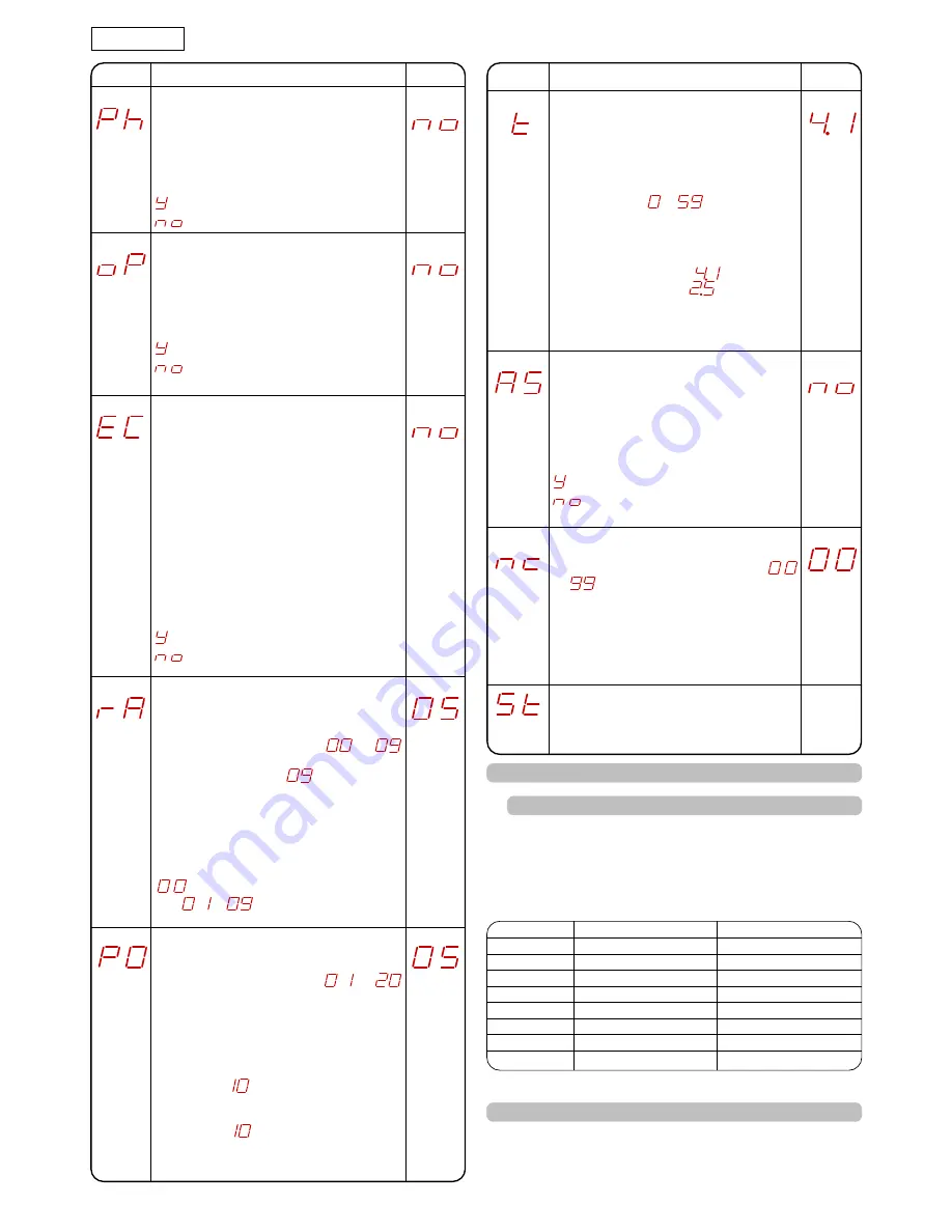
OPENING PHOTOCELLS LOGIC:
Select the tripping mode of the opening
photocells.
They operate for the opening movement
only: they stop the movement and restart
it when they are released, or they reverse it
immediately.
= Reverse immediately when closing
= Restart movement on release
ENCODER:
If the encoder (optional) is used, you may
select its presence.
If the encoder is present and enabled,
"decelerations" and "partial opening" are
controlled by the encoder (see relevant
paragraphs).
The encoder operates as an anti-crushing
device: If the gate strikes an obstacle during
opening or closing, the encoder
immediately reverses gate leaf movement
for 2 seconds. If the encoder operates
again during the 2-seconds reversing time,
it STOPS movement without commanding
any reversing.
= Encoder enabled
= Encoder disabled
DECELERATIONS:
You can select gate deceleration after the
opening and closing limit-switches have
been tripped.
Time can be adjusted from
to
sec. in 0.04-second steps.
The maximum value of
corresponds to
about 7 cm.
If an encoder (optional) is used, the
adjustment is not determined by time but
by motor revs, thus obtaining greater
deceleration precision.
= Deceleration disabled
from
to
= Deceleration enabled
Display
Function
Default
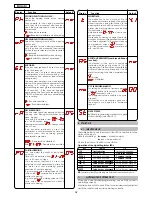
CLOSING PHOTOCELLS LOGIC:
Select the tripping mode of the closing
photocells.
They operate for the closing movement
only: they stop movement and reverse it
when they are released, or they reverse it
immediately.
= Reverse on release
= Reverse immediately when opening
ASSISTANCE REQUEST (combined with next
function):
If activated, at the end of countdown
(settable with the next function i.e. "Cycle
programming") it effects 2 sec. of pre-flashing
at every Open pulse (job request). Can be
useful for setting scheduled maintenance
jobs.
= Active
= Disabled
CYCLE PROGRAMMING:
For setting countdown of system operation
cycles. Settable (in thousands) from
to
thousand cycles.
The displayed value is updated as cycles
proceed.
This function can be used to check use of
the board or to exploit the "Assistance
request".
Display
Function
Default
GATE STATUS:
Exit from programming and return to gate
status viewing (see Chpt 5.1.).
WORK TIME:
We advise you to set a value of 5 to 10
seconds over the time taken by the gate to
travel from the closing limit-switch to the
opening limit-switch and vice versa. This will
protect the motor against any overheating
if a limit-switch fails.
Adjustable from
to
sec. sec. in one-
second steps.
Subsequently, viewing changes to minutes
and tens of seconds (separated by a point)
and time is adjusted in 10 second steps, up
to a maximum value of
minutes.
E.g. if the display shows
, work time is 2
min. and 50 sec.
PARTIAL OPENING:
You can adjust the width of leaf partial
opening.
Time can be adjusted from
to
sec. in 0.1-second steps.
If an encoder (optional) is used, the
adjustment is not determined by time but
by motor revs, thus obtaining greater
precision of partial opening.
E.g. for a gate with a sliding speed of 10 m
/min, value
corresponds to about 1.7
metres of opening.
E.g. for a gate with a sliding speed of 12 m
/min, value
corresponds to about 2
metres of opening.
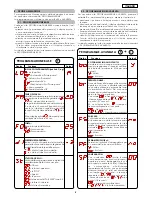
6. START-UP
6.1. INPUTS CHECK
The table below shows the status of the LEDs in relation to to the
status of the inputs.
Note the following:
L
ED
LIGHTED
= closed contact
L
ED
OFF
= open contact
Check the status of the LEDs as per Table.
Operation of the signalling status LEDs
NB.:
The status of the LEDs while the gate is closed at rest are shown in bold.
7.
AUTOMATED SYSTEM TEST
When you have finished programming, check if the system is
operating correctly.
Most important of all, check if the force is adequately adjusted
and if the safety devices are operating correctly.
LEDS
LIGHTED
OFF
FCA
Limit-switch free
Limit-switch engaged
FCC
Limit-switch free
Limit-switch engaged
OPEN B
Command activated
Command inactive
OPEN A
Command activated
Command inactive
FSW OP
Safety devices disengaged
Safety devices engaged
FSW CL
Safety devices disengaged
Safety devices engaged
STOP
Command inactive
Command activated
EDGE
Safety devices disengaged
Safety devices engaged
Summary of Contents for JA383
Page 23: ...note notes note notas anmerkung ...
Page 24: ...note notes note notas anmerkung ...
Page 25: ...note notes note notas anmerkung ...


