background image

4

STB

1 2 3 4 5 6

BWC

IWC

  1 

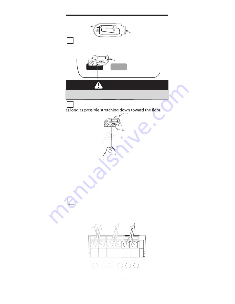
Remove the Network Adapter from its packaging

and insert it into the “NETWORK” port on the powerhead

of your opener with the antenna wire facing down.

  2 

Straighten the antenna wire if needed so that it is 


CONNECTION

PINS

ANTENNA

WIRE

THE NETWORK ADAPTER

  The Intelligent Wall Console receives its power 

through an opener powerhead 

(powered from only 

one opener for a group of up to three)

  1 

Using standard 2 conductor “bell wire,” Attach 

one end to the desired powerhead at terminals 5 & 6, 

as shown.

  NOTE: The IWC can be used 

in place of

 the basic wall 

  console. 

TERMINALS LOCATED INSIDE LIGHT LENS

Safe-T-Beam®

Standard 

Wall Console

INTELLIGENT

WALL CONSOLE

THE INTELLIGENT WALL CONSOLE

NETWORK

BBU

GREEN LIGHT 

SHOULD TURN ON

INSTALLATION (if needed)

•   Are power wires properly connected to terminals 

    5 & 6 on powerhead? 

WARNING


Do NOT place fi ngers, pliers, screw driver or any 

other device into the powerhead. 

Summary of Contents for Intelligent Wall Console

Page 1: ...w geniecompany com SAVE THIS MANUAL FOR FUTURE REFERENCE INSTALLER LEAVE THIS MANUAL WITH HOMEOWNER Genie Genie logo Intellicode Safe T Beam are registered trademarks of GMI Holdings Inc dba The Genie...

Page 2: ...be usedto enable or disable the motion sensor on the opener s powerhead if so equipped The motion sensor will detect movement inside the garage and turn on the opener s work light The name phonenumbe...

Page 3: ...SIDE NETWORK BBU NETWORK ADAPTER PORT must remove rubber cover WARNING Moving Door can cause serious injury or death Wall Console must be mounted in sight of door at least 5 feet above floor and clea...

Page 4: ...wered from only one opener for a group of up to three 1 Using standard 2 conductor bell wire Attach one end to the desired powerhead at terminals 5 6 as shown NOTE The IWC can be used in place of the...

Page 5: ...ecurely in place If using insulated staples be careful not to pinch or sever the wire Make the staples only snug enough to hold the wire 3 Mount the Console using the screws provided A Unlatch and rem...

Page 6: ...ll D Attach wires to terminals on the back of the Console E Attach the Console to the mounting bracket by sliding it down over the upper edge of the bracket and swinging it against the bracket until t...

Page 7: ...7 The Work Light Control buttons can be used to operate the opener s Work Light independently of operating the door opener Work Lights can also be disabled during programming See page 14 Sure Lock ca...

Page 8: ...2 PRESS RELEASE one of the Opener Control buttons on the IWC The BLUE LED on the Network Adapter will go steady ON 3 PRESS RELEASE the same Opener Control button again The BLUE LED on the Network Ada...

Page 9: ...s To begin settings press the MENU ICON 2 Next display is the Console Setup Menu Pressing either SCROLL button will cycle through the following categories Scroll back to SETTINGS from the Console Setu...

Page 10: ...press SELECT YEAR will begin flashing SCROLL to the desired YEAR press SELECT The display will flash DATE SET and return to the SETTINGS menu 1 Pressing the SELECT button to choose TIME FORMAT will pr...

Page 11: ...TIME will present the following display 2 HOURS flashing SCROLL to desired HOUR press SELECT MINUTES will begin flashing SCROLL to desired MINUTES press SELECT Setting AM PM corresponds with setting o...

Page 12: ...settings will be lost It is not recommended to use the Sure Lock in areas of frequent power outages OPENER SETTINGS 2 1 Opener 1 2 or 3 SCROLL to the desired opener press SELECT This determines the o...

Page 13: ...LECT 3 SCROLL to LEARN REMOTE 4 Pressing SELECT will bring up the following display 5 Press the desired remote transmitter button TWICE 6 Press the same button again and the opener will activate The t...

Page 14: ...ose GET FORCE will present the choices Pressing either SCROLL button will cycle between the following choices Pressing SELECT to choose will display the current force level Adjusting the force is cove...

Page 15: ...ing group of sub menus CYCLE COUNT 2 Using the SCROLL button to reach the desired function and press SELECT 1 CYCLE COUNT MSG HISTORY and are MOTOR TEMP displays of information and have no user functi...

Page 16: ...s menu ABOUT IWC 5 4 6 4 5 FCC IC CERTIFIED This device complies with part 15 of the FCC Rules RSS 210 Issue 8 Operation is subject to the following two conditions 1 This device may not cause harmful...

Reviews: