General 90-200 M1 Setup & Operation Manual Download Page 26

26

4.

Do not allow dirt, pitch or gum to build up on the table, blade, guide/thrust bearings. Clean as needed with 
gum and pitch remover.

Note: Do not immerse the bearings in the gum and pitch remover.

5.

To prevent rust and from forming on the unpainted cast iron of the table, and so that the wood slides easily while
cutting, apply a light coating of paste wax or use regular applications of any after-market surface protectant or
rust inhibitor.

REPLACING THE BANDSAW BLADE

The blade should be replaced when worn out.

Refer to the following symptoms to determine whether or not it is time to replace the blade:

- It is not cutting as fast.
- It is not able to follow a cutting line as it used to.

REQUIRED MAINTENANCE

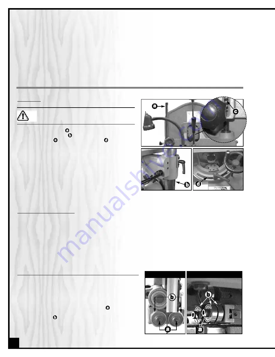
REPLACING THE UPPER / LOWER BLADE GUIDES AND THRUST BEARINGS

Bearings should be verified each time the blade is replaced.
Check if they turn well. If not, the blade will get stuck or jam-
med between them and will wear prematurely.

To replace the upper/lower blade guides, proceed as follows:

1.

Loosen and remove the two Allen bolts 

, using the sup-

plied 5 mm Allen key. Removing the two bolts will free the 
blade guides 

.

2.

Replace the blade guides with new ones and tighten 
with the two Allen bolts.

LOWER BLADE GUIDES

UPPER BLADE GUIDES

LUBRICATION

Disconnect machine from power source, before
performing any lubrication or maintenance.

Keep the blade guard 

and upper frame height adjust-

ment rack and pinions 

as well as the blade tension

adjustment screw 

and the table trunnion 

well greased

and free of dust or debris.

Clean and remove dust, debris, and old grease after every
10-15 hours of use. After cleaning, reapply grease as need-
ed. (Use any all purpose grease.)

The motor and all bearings are sealed and permanently
lubricated – no further lubrication is required. No other part
of this bandsaw needs lubrication.

Summary of Contents for 90-200 M1

Page 1: ...s Quick release blade tension lever 93 1 2 X 3 8 105 X 3 8 blades included Aluminum miter gauge laser line marker and worklight included SPECIFICATIONS WHEEL SIZE 15 375 MM WHEEL SPEED 405 700 RPM MAX...

Page 2: ...handy for future reference Disclaimer The information and specifications in this manual pertain to the unit as it was supplied from the factory at the time of printing Because we are commit ted to mak...

Page 3: ...der our Standard 2 year Limited Warranty or under our Limited Lifetime Warranty all defective parts components or machinery must be returned freight or postage prepaid to General International or to a...

Page 4: ...ents 15 22 Adjusting the 90 table stop and re aligning the angle pointer 15 Blade clearance 15 Removing Installing the blade 16 Blade selection 17 Adjusting blade tension 18 Adjusting blade tracking 1...

Page 5: ...not have a flat surface 16 Hold material firmly against the table 17 Do not work on long stock without adequate support on the out feed end of the table 18 If using a power feeder stop the feeder bef...

Page 6: ...and a power failure still occurs contact a qualified technician or our service department BEFORE CONNECTING THE MACHINE TO THE POWER SOURCE VERIFY THAT THE VOLTAGE OF YOUR POWER SUPPLY CORRESPONDS WI...

Page 7: ...BLE TILT LOCK LEVER GUIDE RAIL TABLE WORKLIGHT BLADE GUARD TABLE INSERT UPPER BLADE GUIDE ASSEMBLY TABLE TILTING SCALE BLADE GUARD LOCK KNOB BLADE GUARD ADJUSTMENT KNOB TRACKING ADJUSTMENT KNOB BLADE...

Page 8: ...HEX HEAD BOLT 4 FLAT WASHER 8 HEX NUT 4 5 MM ALLEN KEY 1 3 MM ALLEN KEY 1 10 MM COMBINATION WRENCH 1 Carefully unpack and remove the unit and its components from its shipping container and check for...

Page 9: ...ble to support the weight of the bandsaw 398 lbs 181 kg and the opera tor Plan for placement within your shop that will allow the operator to work unencumbered and unobstructed by foot traffic either...

Page 10: ...ca binet 2 Insert four hex head bolts and flat washers down through the holes in the legs of the bandsaw and into the base cabinet Then open the door and from the inside tighten four hex nuts with wa...

Page 11: ...re it is stored for shipping 2 From the inside insert the door bolt through the hole in the door into the door knob 3 Tighten the door bolt ATTACHING THE WORKLIGHT 1 Attach the worklight to the mounti...

Page 12: ...ng the two bolts take care in doing so not to mis align the pointer with the zero Once the bolts are tightened recheck for pointer alignment and readjust if needed You will now be able to accurately r...

Page 13: ...he bandsaw Push the RED STOP panel and wait for the blade to come to a complete stop BASIC FUNCTIONS OF THE UNIT This 15 adjustable height wood cutting bandsaw allows the user to adjust the height of...

Page 14: ...CUT The blade guard can be moved up or down to accommodate the height of the work to be cut To prevent the blade which is flexible and which would not otherwise be supported from slipping out of posi...

Page 15: ...now be able to accurately return the table to the 90 position automatically without further adjustments and scale reading for any angle other than 0 will also be accurate ADJUSTING THE 90 TABLE STOP A...

Page 16: ...from 1 4 and 3 8 used for tight radius curves up to 1 2 and 3 4 for larger radius curves or for cutting thicker stock To remove a blade 1 Turn off the bandsaw and unplug the power cord 2 Make sure th...

Page 17: ...cement blades made from high carbon steel can be purchased in a variety of lengths and widths from your General International dealer See Recommended Optional Accessories on page 29 or depending on ava...

Page 18: ...erence and individual work habits A properly tensioned blade is critical to obtaining maximum performance from any bandsaw A properly ten sioned blade will last longer and be much less likely to break...

Page 19: ...ing means centering the blade on the wheels Ideally the blade should stay relatively centered on both the upper and lower wheels Due to natural variations in castings blade thickness or density and ti...

Page 20: ...lade The thrust bearing keeps the blade from moving back and out of position when the work is being fed into the blade and must be very close to the back of the blade to prevent damage to the blade du...

Page 21: ...er guide on the other side of the blade 4 Loosen the lower set screw with the supplied 3 mm Allen key 5 Manually move the guide bearing mounting bracket in or out until the guides are at least 1 32 be...

Page 22: ...d to the slower setting 1570 FPM 480 MPM place the belt on the frontmost set of pulleys as shown in 6 To set the bandsaw speed to the faster setting 2660 FPM 810 MPM place the belt on the rearmost set...

Page 23: ...the bla de guard for depth of cut on page 14 3 If a dust collector is connected to your bandsaw turn it on To reduce the risk of damage to the bandsaw or the workpiece as well as a potential for perso...

Page 24: ...wheels To change a cut turn the workpiece and cut your way out through the waste material area When cutting long curves make relief cuts as you go along CUTTING CIRCLES 1 Adjust the blade guard assemb...

Page 25: ...ockwise to raise or count erclockwise to lower until the upper frame is at the desired height Note The blade length indicator scale on the column is a helpful reference tool showing the correct height...

Page 26: ...the blade is replaced Check if they turn well If not the blade will get stuck or jam med between them and will wear prematurely To replace the upper lower blade guides proceed as follows 1 Loosen and...

Page 27: ...n the upper wheel cover door then unscrew the four Phillips head screws and remove the blade guard 5 Remove the thrust bearing and mounting shaft 6 Use C ring pliers to remove the C ring and slide the...

Page 28: ...r the brush slightly Proceed as follows 1 Loosen the Phillips head screw 2 Slide the brush slightly down along the mounting hole so that a fresh stiffer part of the hairs touch es the wheel tire 3 Tig...

Page 29: ...and a curved resaw attachment 29 Mobile Base 50 025 Easily roll your bandsaw anywhere in your shop Load capacity 500 LBS Wheels lock when equipment is in use 93 1 2 LONG item 90125 B14 Width 1 4 TPI 6...

Page 30: ...13 50 48 40 193 147 117 114 148 146 118 119 144 145 143 117 118 140 164 165 166 164 142 40 141 152 138 118 139 119 146 149 114 156 157 138 160 161 158 159 118 119 117 162 163 114 120 121 168 104 174...

Page 31: ...92 78 93 85 107 101 95 94 96 97 98 108 102 100 99 103 102 109 110 111 105 104 104 153 114 117 125 124 123 122 112 116 101 126 74 127 128 74 114 115 135 136 114 140 134 133 131 125 129 132 102 114 138...

Page 32: ...OB LOWER DOOR DOOR BOLT TIRE LOWER WHEEL WHEEL PULLEY BEARING V BELT KEY LOWER WHEEL SHAFT DOOR CLIP DOOR CLIP MOUNTING POST MOTOR PULLEY GEAR SHAFT GEAR SHAFT 10T 25T SPROCKET 10T SPROCKET SPROCKET C...

Page 33: ...ING BLADE GUIDE POST UPPER BLADE GUARD RIGHT LOWER BLADE GUARD RIGHT BLADE GUARD MOUNTING PLATE MICRO ADJUSTMENT KNOB MICRO ADJUST SHAFT UPPER GUIDE BEARING HOLDER BEARING SHAFT BEARING BLADE GUIDE HO...

Page 34: ...HER PHILLIPS HEAD SCREW FLANGE SCREW E RING SET SCREW RATCHET LEVER HEX NUT SET SCREW PHILLIPS HEAD SCREW BRUSH HOLDER WHEEL BRUSH FLAT WASHER LOCK WASHER SWITCH PLATE PHILLIPS HEAD SCREW PHILLIPS HEA...

Page 35: ...SPACER SET SCREW FLAT WASHER ALLEN KEY 5MM ALLEN KEY 3MM BASE CABINET BASE CABINET DOOR HEX HEAD BOLT FLAT WASHER HEX NUT PIN SET SCREW KEY MOUNTING PLATE FOR LEFT BLADE GUARD BLADE TRACKING WINDOW PV...

Page 36: ...HOUSING CAPACITOR CAPACITOR COVER CAPACITOR HOUSING CENTRIFUGAL SWITCH ASSEMBLY TERMINAL STRAIN RELIEF BUSHING BUSHING COVER LOWER COVER UPPER PHILLIPS HEAD SCREW FLANGE SCREW FLANGE SCREW FLANGE SCR...

Page 37: ...2 05 90200 92 06 90200 92 07 90200 92 08 90200 92 09 90200 92 10 90200 92 11 DESCRIPTION HANDLE FLAT WASHER MITER GAUGE HEAD POINTER GUIDE BAR T SLOT WASHER SCREW SCREW STEEL BALL SPRING SET SCREW QTY...

Page 38: ...ON GUIDE RAIL LONG GUIDE RAIL SHORT SLIDE BRACKET FENCE BRACKET FENCE BODY MAGNIFYING GLASS LOCK KNOB HEX HEAD BOLT PHILLIP HEAD SCREW LOCK KNOB HEX HEAD BOLT CAP SCREW L PLATE FLAT WASHER MEASURING T...

Page 39: ...39 NOTES...

Page 40: ...ial number of the machine and part number Also a brief description of each item and quantity desired 8360 Champ d Eau Montreal Quebec Canada H1P 1Y3 Tel 514 326 1161 Fax 514 326 5565 Parts Service Fax...

Reviews: