47
Model FL4000H
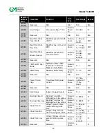
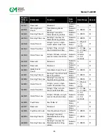
Register
Address
(Hex)
Parameter
Function
Data
Type
Data Range Access
0x00BC
Clock Time Hi
Hi byte = year, Lo byte
month: Maintenance
clock time
Numeric
Value
1 –99 year,
1– 12
month
R
0x00BD
Clock Time Mid
Hi byte = Day, Lo byte
Hour: Maintenance clock
time
Numeric
Value
1 – 31 day,
0 – 23 hour
R
0x00BE
Clock Time Low
Hi byte = Minute, Lo byte
second: Maintenance
clock time
Numeric
Value
0 – 59
minutes
0 – 59
seconds
R
0x00BF Reserved
Reserved
Numeric
Value
0 R
0x00C0
Maintenance
Event Count
Total Maintenance Event
Count
Numeric
Value
0 - 65535
R
0x00C1
Reset Event
Counter
Reset All Events Counter
to 0
Numeric
Value
0 - 65535
W
4.10
Command Register Details
The following sections provide a detailed description of each user Modbus command register.
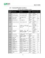
4.10.1 Analog (0x0000)
A read returns a value, which is proportional to the 0-20 mA output current. The value
corresponds to a scaling of 0-65535 decimal.
4.10.2 Operating Mode (0x0001)
A read returns the present mode of the FL4000H. A write command changes the mode to the
requested mode.
NOTE:
Returns an Exception Code 03 (Illegal Data Value) if an illegal write is requested.
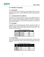
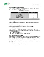
Table 31: Status Mode Values
Mode
Decimal Value
Power-Up Delay
1
Warn Non-Latching Only
2
Warn and Alarm Non-latching
3
Warn Latching Only, Alarm Off
4
Alarm Latching Only
5
Warn & Alarm Latching
6
Ready State
7
Alarm Test
10
COPM Fault Detected
11
Warn Latching, Alarm Non-latching, Alarm On
12
TEST LAMP Cycle
13
TEST LAMP Cycle – Fire
14
Summary of Contents for FL4000H
Page 2: ...ii Model FL4000H This page intentionally left blank ...
Page 8: ...viii Model FL4000H Figure 2 Mounting Instruction Figure 3 Wall Mounting Assembly ...
Page 28: ...28 Model FL4000H Figure 16 Detector Mounting and Installation ...
Page 61: ...61 Model FL4000H 6 2 Final Assembly Figure 26 FL4000H Cross Section View ...


