background image


12 


  Model FL4000H

Silicone Room Temperature Vulcanization (RTV) is not an approved moisture barrier. If used, 
damage to internal components will arise. 

Damage to the FL4000H housing where any internal components or protective seals are broken, 
compromises the safety and usability of the device. An FL4000H with a damaged or open housing 
should not be used in a hazardous environment. Such damage includes fractures in the housing, 
cracks in any internal components, or cracks in the protective seals. 

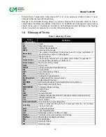
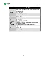
1.4    Glossary of Terms 

Table 1: Glossary of Terms 

Term / 

Abbreviation  

Definition 

Amps 

AC 

Alternating Current 

ANN 

Artificial Neural Network 

AWG 

American Wire Gauge 

Baud Rate 

The number of signal level changes per second in a line, regardless of 
the information content of those signals 

bps 

Bits per second 

Cable Armor 

Cable having interlocked or corrugated armor where it is essential to 
provide positive grounding of cable armor 

Cable Screen 

Mesh surrounding a cable 

COM 

DC Ground 

COPM 

Continuous Optical Path Monitoring 

CR 

Control Room 

CRC 

Cycle Redundancy Check 

DC 

Direct Current 

DCS 

Distributed Control System 

De-Energized 

To disconnect from a power source 

DSP 

Digital Signal Processor 

EEPROM 

Electrically Erasable Programmable Read-Only Memory 

EMI 

Electromagnetic Interference 

ENERGIZED 

To apply voltage or energy  

FOV 

Field of View 

FS 

Full Scale 

GM 

General Monitors 

HART 

Highway Addressable Remote Transducer-communication protocol 

Hex 

Hexadecimal Number 

I / O 

Input / Output 

Instrument Earth 

Grounded using a grounding strap 

Latching 

Refers to relays remaining in the “on” state even after the “on” condition 
has been removed 

LED  

Light Emitting Diode 

LSB 

Least Significant Bit 

mA 

Milli-Amps refers to 1/1000 of an Amp  

Master 

Controls one or more devices or processes 

Modbus 

Master-slave messaging structure 

N/A 

Not Applicable 

NC 

Normally Closed 

NO 

Normally Open 

Summary of Contents for FL4000H

Page 1: ...rposes and to the extent specifically authorized in writing by General Monitors Instruction Manual 7 16 General Monitors reserves the right to change published specifications and designs without prior notice MANFL4000NH Part No MANFL4000NH Revision N 7 16 MODEL FL4000H Multi Spectral Infrared Flame Detector ...

Page 2: ...ii Model FL4000H This page intentionally left blank ...

Page 3: ...ing Safety Systems 11 1 3 Special Warnings 11 1 4 Glossary of Terms 12 2 0 PRODUCT OVERVIEW 14 2 1 General Description 14 2 2 Features and Benefits 14 2 3 Applications 15 2 4 Principle of Operation 15 3 0 INSTALLATION 21 3 1 Unpacking the Equipment 21 3 2 Required Tools 21 3 3 Detector Location Guidelines 22 3 4 Field Wiring Procedure 26 3 5 Detector Mounting and Installation 27 3 6 Terminal Conne...

Page 4: ...tions 43 4 10 Command Register Details 47 5 0 MAINTENANCE 58 5 1 General Maintenance 58 5 2 Cleaning the Sapphire Window 58 5 3 Sensitivity Check 59 5 4 Storage 59 6 0 TROUBLESHOOTING 60 6 1 Troubleshooting Chart 60 6 2 Final Assembly 61 7 0 CUSTOMER SUPPORT 62 7 1 Other Sources of Help 62 8 0 APPENDIX 63 8 1 Warranty 63 8 2 Specifications 63 8 3 Regulatory Information 65 8 4 Response to False Sti...

Page 5: ...w Sensitivity 24 Figure 12 Vertical FOV n Heptane High Sensitivity 24 Figure 13 Vertical FOV n Heptane Medium Sensitivity 25 Figure 14 Vertical FOV n Heptane Low Sensitivity 25 Figure 15 FL4000H Housing 26 Figure 16 Detector Mounting and Installation 28 Figure 17 Dimensional Drawing 29 Figure 18 Wire Strip Lengths 29 Figure 19 Base Housing and Terminal Blocks 30 Figure 20 Terminal Connections 31 F...

Page 6: ...35 Table 18 Maximum Cable Lengths for 24 VDC 35 Table 19 Modbus Terminals 36 Table 20 Chassis Ground Terminal 36 Table 21 Dipswitch Options 37 Table 22 Selectable Baud Rates 39 Table 23 Selectable Data Formats 39 Table 24 Modbus Read Register s Request 40 Table 25 Modbus Read Register s Response 40 Table 26 Modbus Write Register Request 41 Table 27 Modbus Write Register Response 41 Table 28 Except...

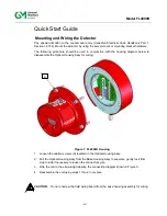
Page 7: ...am below to disassemble the Optical Housing Assy for wiring Figure 1 FL4000H Housing 1 Loosen the captive screws A located on the Optical Housing Assy 2 Pull the Optical Housing Assy from the Base Housing Assy to separate gently rock from side to side if necessary to loosen the connector s grip 3 Wire the unit to the site wiring following the connection diagram shown in Figure 5 4 Reassemble the u...

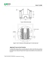
Page 8: ...viii Model FL4000H Figure 2 Mounting Instruction Figure 3 Wall Mounting Assembly ...

Page 9: ...tor Two light emitting diodes LED s are visible through the window Immediately upon powering up the detector both LED s will start blinking alternately for 15 seconds The unit will then enter the Ready mode During the Ready mode the green LED will flash off 0 5 seconds every 5 seconds 1 Recommended by Underwriters Laboratories of Canada ...

Page 10: ...ings User Menus and Modbus notations These conventions are described below Notes Cautions and Warnings NOTE Notes provide supplementary details such as exception conditions alternate methods for a task time saving tips and references to related information CAUTION These notices describe precautions to prevent hazardous conditions that may damage the equipment WARNING These notices describe precaut...

Page 11: ...according to the manufacturer s recommendations and instructions Proper system operation should be verified by performing a full functional test of all component devices of the safety system ensuring that the proper alarm levels occur Fault Malfunction circuit operations should be verified 1 3 Special Warnings WARNING Toxic combustible and flammable gases and vapors are dangerous Extreme caution s...

Page 12: ...locked or corrugated armor where it is essential to provide positive grounding of cable armor Cable Screen Mesh surrounding a cable COM DC Ground COPM Continuous Optical Path Monitoring CR Control Room CRC Cycle Redundancy Check DC Direct Current DCS Distributed Control System De Energized To disconnect from a power source DSP Digital Signal Processor EEPROM Electrically Erasable Programmable Read...

Page 13: ...Logic Controller ppm Parts per million RFI Radio Frequency Interference RMS Root Mean Square ROM Read Only Memory RTV Room Temperature Vulcanization Safety Earth Grounded to the earth Slave One or more devices or processes controlled by a master controller SMT Surface Mount Technology SPAN Value The programmed range of measurable parts per million SPDT Single Pole Double Throw SPST Single Pole Sin...

Page 14: ...ection with uniform sensing and no blind spots Modular Design Results in low maintenance and reduced total cost of ownership Compact Unitized Design Enhances ease of installation and maintenance Continuous Optical Path Monitoring COPM Regularly monitors the optical path to ensure the window is not dirty 0 20 mA Analog Output Transmits alarm and fault indication to a remote display computer or othe...

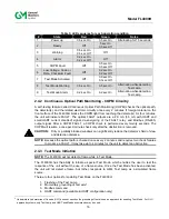
Page 15: ... sensors for different IR wavelengths and characteristics This combination provides a flame detection system which is highly immune to false alarms The ANN network classifies the output signals from the detector as either fire or no fire The unit then produces the following output signals 0 to 20 mA signal 3 5 or 1 25 to 20 mA with optional HART protocol Immediate WARN relay contacts Time delayed ...

Page 16: ...ULT relay and Modbus RS 485 output signal After a COPM FAULT a COPM check is performed every twenty seconds The COPM will resume a once per 2 minute check only after the obstruction is removed CAUTION Dirty or partially blocked windows can significantly reduce the detector s field of view and detection distance NOTE Because the optical path is checked once every 2 minutes and requires two check fa...

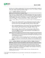
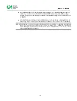
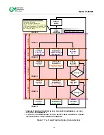
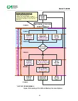
Page 17: ... the unit will return to Ready Mode by dropping the analog output to 4 3 mA restoring the LED flashing to Ready shown in sequence 2 Table 3 and setting the relay to Ready State The FL4000H has now returned to flame detection status NOTE After the test is initiated via the Test Lamp all other commands are ignored until the Test Mode is over While in Test Mode the unit will not detect flames Interru...

Page 18: ... After 4 25 minutes in Phase 4 the FL4000H returns to Ready Mode indicating 4 3 mA at the analog output restoring the LED flashing to Ready shown in sequence 2 Table 3 NOTE After the test is initiated via wire or Modbus all other commands are ignored until the Test Mode is over While in Test Mode the unit will not detect flames Interruption of the Test Lamp flashing for more than 3 seconds will re...

Page 19: ...R SETTING VIA DIP SWITCH 0 8 10 OR 14 SEC OR MODBUS 0 30 SEC FACTORY PROGRAMMABLE 2 SEC TEST LAMP CONTINUOUSLY FLASHING 0 30 SEC 4 25 MIN 5 8 SEC PHASE 0 PHASE 1 PHASE 2 PHASE 3 PHASE 4 PHASE 0 TEST LAMP IS POINTED ON FL4000 Latching YES Latching YES IGNORED MISUSE CONDITIONS GROUND TEST WIRE HOLD TEST WIRE GROUNDED RESEND TEST MODE MODBUS COMMAND TEST LAMP FLASHING IN TL103 MODE FOR TL104 OR IN S...

Page 20: ...ST LAMP CONTINUOUSLY FLASHING TEST LAMP NOT FLASHING 5 8 SEC 4 25 MIN INSTANT IN TEST MODE FACTORY PROGRAMMABLE PHASE 0 PHASE 1 PHASE 2 YES PHASE 3 PHASE 4 PHASE 0 ANALOG OUTPUT 1 5 mA 3 5 mA with HART RELAY SETTING Ready IGNORED MISUSE CONDITIONS REPEAT GROUNDING OF TEST WIRE HOLD TEST WIRE GROUNDED RESEND TEST MODE MODBUS COMMAND TEST LAMP FLASHING IN TL103 MODE FOR TL104 OR IN SWITCH POSITIONS ...

Page 21: ...ily removing the supply voltage for at least 70 ms with a decline of operation voltage of no less than 3 VDC 3 1 Unpacking the Equipment All equipment shipped by General Monitors is packaged in shock absorbing containers that protect against physical damage The contents should be carefully removed and checked against the enclosed packing list If any damage has occurred or there is any discrepancy ...

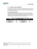
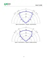
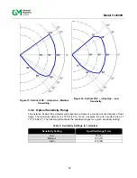
Page 22: ... going through the center axis of the detector and vertical FOV is measured in the vertical plane going through the same axis Both horizontal and vertical FOV are defined for high medium and low sensitivity settings of the FL4000H as shown in Figure 9 through Figure 14 Table 5 Maximum Specified Fields of View at High Sensitivity6 Field of View Horizontal Field of View Vertical Max Specified Range ...

Page 23: ...23 Model FL4000H Figure 9 Horizontal FOV n Heptane High Sensitivity Figure 10 Horizontal FOV n Heptane Medium Sensitivity ...

Page 24: ...24 Model FL4000H Figure 11 Horizontal FOV n Heptane Low Sensitivity Figure 12 Vertical FOV n Heptane High Sensitivity ...

Page 25: ...e detector will respond to a flame is a function of the intensity of that flame The maximum distance is 210 ft 64 0 m for an n heptane fire with a surface area of 1 ft2 0 092 m2 The following table shows the specified ranges for a given sensitivity setting Table 6 Sensitivity Settings for n Heptane Sensitivity Setting Specified Range ft m Low 60 18 Medium 120 37 High 210 64 ...

Page 26: ...s For this condition a cover for shade may be required to bring the detector temperature within specifications As with any cover or object near by make sure the field of view of the detector is not obstructed Avoid conditions of ice build up on the optical detector windows Complete icing over of the IR detector window can result in fault conditions Modulated reflected sunlight shining at the face ...

Page 27: ...bration and convenient for visual inspection and cleaning The detector s should be tilted downward so that dust or moisture does not accumulate on the sapphire window The detector s should be mounted in locations which will inhibit people or objects from obscuring the detector s FOV NOTE Frequent inspection cleaning and sensitivity checking is suggested for detectors mounted in dirty environments ...

Page 28: ...28 Model FL4000H Figure 16 Detector Mounting and Installation ...

Page 29: ...rminal Block The Terminal Block is located in the Base Housing Assembly and accepts 14 AWG 2 08 mm2 to 22 AWG 0 33 mm2 stranded or solid core wire Each wire should be stripped as shown in Figure 18 Figure 18 Wire Strip Lengths To connect the wire to the Terminal Block insert the conductor into the connection space Figure 20 and tighten the corresponding screw terminal ...

Page 30: ...N 2 1 FLT 2 9 WARN 1 2 FLT 1 8 WARN C 3 FLT C 7 ALM C 4 TEST_10 Test Mode 6 ALM 1 5 COM1 DATA1 5 ALM 2 6 COM1 DATA1 4 RLY_10 Relay Reset 7 0 20mA 3 COM2 DATA2 8 24 VIn 2 COM2 DATA2 9 GND COM 1 CAL_ IO 10 CHGND CHASGND Chassis Ground There are twenty possible terminal connections Sections 3 6 1 3 6 2 and 3 6 4 provide a description and specification for each connection ...

Page 31: ...dbus RS 485 or the user selectable dipswitch Section 3 7 Note that a minimum time delay of 8 seconds can be applied if the flame source is removed within 50 of set delay time from the start of flame Please refer to Sec 3 7 1 If set via Modbus below 8 seconds the detector may go into alarm even if the flame source is removed within 50 of the delay time The ALARM output can be normally energized or ...

Page 32: ...lly energized or de energized latching or non latching These options are also set via Modbus or by a dipswitch Section 3 7 The WARN relay contact ratings are 8 A 250 VAC and 8 A 30 VDC Refer to Figure 20 for all relay connections 3 6 3 Alarm Wiring Relay Protection Inductive loads bells buzzers relay contractors solenoid valves etc connected to the Alarm Warn and Fault relays must be clamped down ...

Page 33: ...Reset Terminal Terminal Block Connection Point Block Name Setting P2 Term 4 RLY_IO Relay Reset The RESET when activated returns a latched ALARM and or WARN output that is no longer valid to its original state For this RESET function place one contact of a SPST single pole single throw normally open momentary switch to P2 Terminal 4 and the other contact to P1 terminal 9 GND To activate press and r...

Page 34: ... the Flame Detector The Alarm Test will activate the WARN and ALARM relay outputs as well as the appropriate analog output The Flame Detector will remain in this state until the switch is released or until 3 minutes has elapsed NOTE The latching WARN and or ALARM will have to be reset manually RESET RELAYS TB2 PIN 4 TEST MODE TB1 PIN 4 ALARM TEST SWITCH TEST MODE SWITCH RESET RELAYS SWITCH NOTE AL...

Page 35: ...ing with 250 input impedance devices the following maximum cable lengths apply maximum 50 loop Table 16 Maximum Cable Lengths for 250 Inputs AWG Feet Meters 14 9 000 2 750 16 5 800 1 770 18 3 800 1 160 20 2 400 730 22 1 700 520 3 6 10 Power Table 17 Power Terminals Terminal Block Connection Point Block Name Setting P1 Term 8 24IN 24 VIn VDC P1 Term 9 GND Ground COM Table 17 shows the power connect...

Page 36: ... of the detector to electric surges electromagnetic interference and ultimately damage to the instrument 3 7 Switch Selectable Options All settings on the FL4000H are selected via a dipswitch on the Power Relay board or via Modbus overrides switch settings To set these options remove the detector head from the Base Assembly and locate the dipswitch Figure 23 On the dipswitch ON CLOSED means the sw...

Page 37: ...ensitivity 2 1 4 0 Second Alarm Time Delay 3 and 4 5 8 Second Alarm Time Delay 4 3 6 10 Second Alarm Time Delay 3 and 4 7 14 Second Alarm Time Delay 3 4 8 ALARM Non Latching 5 9 ALARM Latching 5 10 WARN Non Latching 6 11 WARN Latching 6 12 ALARM Normally Energized 7 13 ALARM Normally De Energized 7 14 WARN Normally Energized 8 15 WARN Normally De Energized 8 ...

Page 38: ...0 5 seconds Upon completion of the power on sequence the green LED will alternate on for 5 seconds and off for 0 5 seconds to indicate a READY status 3 9 Power up Grounding of the Test and Relay Reset Lines During power up grounding the reset relay line for approximately 1 second forces the Modbus parameters on both channels to go to their default values of 19 200 Baud 8 N 1 format and Unit ID 1 D...

Page 39: ...the address for channel COM2 4 3 Baud Rate The FL4000H baud rate is selectable using either the Modbus communications interface The selectable baud rates are 38 400 19 200 9 600 4 800 or 2 400 bits per second bps The factory set baud rate is 19 200 bps Register 0x0B is used to modify the baud rate for comm channel 1 and register 0x30 is used to modify the baud rate for comm channel 2 The selectabl...

Page 40: ...ex CRC Lo Byte 8th CRC Hi 00 FF Hex CRC Hi Byte Address 0 is reserved for Broadcast Mode and is not supported at this time A maximum of 69 registers can be requested during a single block of time Upon receiving a valid read register request from the master device the FL4000H will respond with a message Table 25 If the query generates an error an exception message is returned to the master device S...

Page 41: ...Used by FL4000H 4th Register Address Lo 00 FF Hex FL4000H Register Address Lo Byte 5th Preset Data Hi 00 FF Hex FL4000H Hi Byte Command Data 6th Preset Data Lo 00 FF Hex FL4000H Lo Byte Command Data 7th CRC Hi 00 FF Hex CRC Hi Byte 8th CRC Lo 00 FF Hex CRC Lo Byte Address 0 is reserved for Broadcast Mode and is not supported at this time 4 8 Exception Responses and Exception Codes 4 8 1 Exception ...

Page 42: ...n Response Byte Modbus Range Referenced to FL4000H 1st Slave Address 1 247 Decimal FL4000H ID Address 2nd Function Code 83 or 86 Hex Preset Single Registers 3rd Exception Code 01 06 Hex Appropriate Exception Code See Below 4th CRC Hi 00 FF Hex CRC Hi Byte 5th CRC Lo 00 FF Hex CRC Lo Byte Address 0 is reserved for Broadcast Mode and is not supported at this time 4 8 2 Exception Code Exception Code ...

Page 43: ...bles Bit Map 0 Options read from DIP 1 means from Flash R W 0x0008 Unit Options Indicates which options are configured Numeric Value R W 0x0009 COM1 Address Set view address on Modbus channel 1 Numeric Value 1 247 R W 0x000A Reserved N A N A N A N A 0x000B COM1 Baud Rate Set view baud rate on Modbus channel 1 Numeric Value Table 33 R W 0x000C COM1 Data Format Set view data format on Modbus channel...

Page 44: ...tal communication errors received on Comm 1 Numeric value 0 65535 R 0x0025 CRC errors LO for serial channel Number of CRC LO errors on user Modbus channels Numeric value 0 65535 R 0x0026 CRC errors HI for user serial channel Number of CRC HI errors on user Modbus channels Numeric value 0 65535 R 0x0027 Total Overrun Errors COM1 Only Total Overrun errors received on comm channel 1 Numeric value 0 6...

Page 45: ...Numeric Value 0 1 R W 0x005B Alarm Delay Read Set Alarm Delay Numeric Value 0 30 R W 0x005C 0x0090 Reserved N A N A N A N A 0x009A Power Cycled Flag Time Reset After power Cycled Numeric Value 0 Time not Reset 1 Time Reset R 0x009B 0x009F Reserved N A N A N A N A 0x00A0 Event Index Index of Logged Events Numeric Value 0 9 R W 0x00A1 Running Time Hi Running Time Hi for Warning Event log entries Num...

Page 46: ...ed Reserved Numeric Value 0 R 0x00B0 Alarm Event Count Total Alarm Event Count Numeric Value 0 65535 R 0x00B1 Running Time Hi Running Time Hi for Fault Event log entries Numeric Value 0 65535 R 0x00B2 Running Time Low Running Time Low for Fault Event log entries Numeric Value 0 65535 R 0x00B3 Clock Time Hi Hi byte year Lo byte month Fault clock time Numeric Value 1 99 year 1 12 month R 0x00B4 Cloc...

Page 47: ... W 4 10 Command Register Details The following sections provide a detailed description of each user Modbus command register 4 10 1 Analog 0x0000 A read returns a value which is proportional to the 0 20 mA output current The value corresponds to a scaling of 0 65535 decimal 4 10 2 Operating Mode 0x0001 A read returns the present mode of the FL4000H A write command changes the mode to the requested ...

Page 48: ...n of the window or detector malfunction Cleaning the window or removing the obstacle can clear a COPM fault caused by a window obstruction Bit 7 is 1 if a COPM fault exists Bits 0 1 2 or 3 indicate which of the detectors are in Fault 4 10 7 Dipswitch Override 0x0007 A read indicates the status of the dipswitch override bit A write command changes the state of the bit Figure 24 When the dipswitch o...

Page 49: ...nsitivity Relay Delay Relay Latching Non Latching and Relay Energized De Energized features either from the Options dipswitch or the FLASH depending on the setting of the dipswitch override bit listed above A write command changes the settings for the FLASH only when the dipswitch override bit is enabled The bits 0 7 in the register map directly to the dipswitches 1 8 as shown in Table 21 NOTE If ...

Page 50: ...to a default of 19 2K when the red and green LED s flash alternately after approximately 1 second at which time the RESET input can be released from ground 4 10 11 COM1 Data Format 0x000C A read command returns the current data format for COM1 channel Write command changes the data format to the requested values Valid settings are shown in Table 34 Default format is 8 N 1 Table 34 Selectable Data ...

Page 51: ...dition the function also activates the corresponding LED sequence and analog output Upon completion of the test a zero should be written to the register to conclude the Alarm Test If the relays are configured in a latching configuration refer to Section 4 10 16 to reset the relays and the alarm condition 4 10 18 Clear COPM Faults 0x0013 Writing a 1 to the register activates the Clear COPM Faults f...

Page 52: ... occurred in the FL4000H The maximum count is 65535 after which the counter resets to zero and begins counting anew NOTE An overrun error occurs when a subsequent received data byte overwrites an earlier unprocessed data byte As a result one of the received data bytes will be corrupted 4 10 29 Total Framing Errors COM1 and COM2 0x0029 A read indicates the number of Comm 1 and Comm 2 Framing Errors...

Page 53: ...L4000H will default to 8 N 1 Valid settings are shown in Table 33 4 10 35 Set Read Real time Clock Year Month 0x0047 This is used to read write the real time clock The high byte will be the year minus 2000 The low byte will be a value from 1 to 12 4 10 36 Set Read Real time Clock Day Hour 0x0048 This is used to read write the real time clock The high byte will be the day of the month from 1 to 31 ...

Page 54: ... and 9 refers to the least recent event stored in the log For example to read the most recent Warning event in the Warning event log set this register to 0 and then read registers 0xA1 and 0xA2 for the running time in seconds or read registers 0xA3 0xA4 and 0xA5 for the clock time There is also a warning counter which gives the total number of warnings received by the system with a maximum of 6553...

Page 55: ... 1 2000 This register should be read before register 0xAA 4 10 51 Alarm Running Time in Seconds Low Word 0x00AA This register reads the low word of the running time in seconds when the alarm event occurred This time is in seconds since January 1 2000 This register should be read only after register 0xA9 4 10 52 Alarm Clock Time Year Month 0x00AB These registers are described in Table 35 as item nu...

Page 56: ... register is described in Table 32 4 10 64 Reserved 0x00B7 This register returns the value 0 4 10 65 Total Fault Event Counter 0x00B8 This reads the total number of fault events have been stored in the unit 4 10 66 Maintenance Running Time in Seconds Hi Word 0x00BA This register reads the hi word of the running time in seconds when the maintenance event occurred This time is in seconds since Janua...

Page 57: ...ister returns the value 0 4 10 72 Total Maintenance Event Counter 0x00C0 This reads the total number of maintenance events have been stored in the unit 4 10 73 Reset All Event Counters 0x00C1 Writing to this register resets all event counters to zero ...

Page 58: ... detector is located in a particularly dirty environment 5 2 Cleaning the Sapphire Window A clean soft lint free cloth tissue or cotton swab should be used to apply the cleaning solution The window is not glass it is made from sapphire The cleaning solution should be General Monitors P N 10272 1 Industrial Strength Windex with Ammonia D Do not touch the window or COPM reflector with fingers 1 Wet ...

Page 59: ... General Monitors Test Lamp and or the ALARM TEST function Section 3 6 7 should be used Refer to Section 8 5 for details on Test Lamps 5 4 Storage The FL4000H should be stored in a clean dry area and within the temperature and humidity ranges quoted in Section 8 2 5 Environmental Specifications ...

Page 60: ...l 0 mA 3 5 or 1 25 mA with HART and green LED in window is rapidly blinking Low voltage FAULT voltage at unit is approximately 18 5 VDC Be sure that the unit is powered with at least 24 VDC under load Analog output signal 0 mA 3 5 or 1 25 mA with HART and green LED in window is rapidly blinking 24 VDC verified Flash Checksum Not OK Re cycle power to the unit Analog output signal 0 mA 3 5 or 1 25 m...

Page 61: ...61 Model FL4000H 6 2 Final Assembly Figure 26 FL4000H Cross Section View ...

Page 62: ...91 H6P2 Phone 353 91 751175 SINGAPORE No 2 Kallang Pudding Rd 09 16 Mactech Building Singapore 349307 Phone 65 6 748 3488 MIDDLE EAST PO Box 54910 Dubai Airport Free Zone United Arab Emirates Phone 971 4294 3640 Additional locations can be found on our web site www MSAsafety com 7 1 Other Sources of Help Extensive documentation white papers and product literature for our complete line of safety pr...

Page 63: ...ral Monitors disclaims all warranties with regard to the products sold including all implied warranties of merchantability and fitness and the express warranties stated herein are in lieu of all obligations or liabilities on the part of General Monitors for damages including but not limited to consequential damages arising out of or in connection with the use or performance of the product 8 2 Spec...

Page 64: ...mA FAULT signal 0 to 0 2 mA 3 5 mA 1 25 mA COPM fault signal 2 0 0 2 mA 3 5 mA 2 0 0 2 mA Ready signal 4 3 0 2 mA WARN signal 16 0 0 2 mA ALARM signal 20 0 0 2 mA Relay Contact Ratings 8 A 250 VAC 8 A 30 VDC Resistive MAX RS 485 Output Modbus 128 units in series MAX 247 units with repeaters 2400 4800 9600 19200 and 38400 Baud See Terminal Connections 3 4 for Alarm Output Connections Two LED s indi...

Page 65: ...ensitivity and Class 2 for Low Sensitivity 8 3 2 Classification Area and Protection Methods The FL4000H is certified as follows Protection Method Explosion proof Flame proof Dust Ignition proof Temperature Class T5 Tamb 40 C to 80 C Area Classifications Class I Division 1 Groups B C and D Class II Division 1 Groups E F and G Class III Zone 1 Group IIC per ATEX IECEx Zone 21 Group IIIC per ATEX IEC...

Page 66: ... Fluorescent lamp 2 40 W bulbs 1 0 3 No alarm 1 0 3 No alarm 500 W halogen lamp 2 0 6 No alarm 1 0 3 No alarm Sunlight reflected 6 1 8 No alarm 6 1 8 No alarm Sunlight direct No alarm No alarm Hot plate 200 C 3 0 9 No alarm 1 0 3 No alarm Arc welding 6012 1 8 in 180 200 A DC 5 1 5 No alarm 11 3 4 No alarm Arc welding 6012 1 8 in 190 A AC 5 1 5 No alarm 9 2 7 No alarm Arc welding 7014 1 8 in 180 20...

Page 67: ...35 10 7 Fluorescent lamp unmodulated 2 5 0 8 1 x 1 ft2 heptane 35 10 7 Fluorescent lamp modulated 2 5 0 8 1 x 1 ft2 heptane 80 24 4 Halogen lamp unmodulated 2 0 6 1 x 1 ft2 heptane 70 21 3 Halogen lamp modulated 4 1 2 1 x 1 ft2 heptane 35 10 7 Arc welding 7014 3 16 in 190 A unmodulated 12 3 7 1 x 1 ft2 heptane 80 24 4 Arc welding 7014 3 16 in 190 A modulated 15 4 6 1 x 1 ft2 heptane 80 24 4 In gen...

Page 68: ...ith HART and small HART current disabled While the FL4000H is activated in test mode via the Test Lamp the FL4000H will detect the TL105 Test Lamp as a flame source The analog output and relays will respond as if a flame were present The analog output will rise from 1 5 mA 3 5 mA with HART and small HART current disabled to 16 mA warning condition and then to 20 mA alarm Relays will trip In additi...

Page 69: ... the plug after charging is complete It is recommended that the Test Lamp be kept on charge when not in use to prevent excessive battery discharge The batteries may be charged an average of 500 times before the battery pack must be replaced 8 5 3 Mounting Bracket A mounting bracket is available to mount the FL4000H to a wall pole etc The mounting bracket design allows for optical alignment adjustm...

Page 70: ...70 Model FL4000H 9 0 Appendix A Rotary Switch shown in position 1 for testing FL3100 Flame Detectors for FL4000H use position 4 Figure 28 Functional Board Located Under TL105 Lamp Assembly ...

Page 71: ...L3001 35 FL3001 triggers into alarm mode FL3002 10 FL3002 triggers into alarm mode FL3100 20 FL3100 triggers into alarm mode FL3101 35 FL3101 triggers into alarm mode FL3102 10 FL3102 triggers into alarm mode FL3110 20 FL3110 triggers into alarm mode FL3111 35 FL3111 triggers into alarm mode FL3112 8 FL3112 triggers into alarm mode FL4000H 35 High Sensitivity FL4000H enters test mode FL4000H 18 Me...

Page 72: ...es EU Member states shall dispose according to WEEE regulations For further WEEE disposal information please visit www MSAsafety com All other countries or states please dispose of in accordance with existing federal state and local environmental control regulations ADDENDUM ...

Reviews: