background image


3

•  Before installing or servicing this (and related) equipment, make 

sure that all power voltage supplies are positively turned off at 

their source. Failure to do so will result in hazardous and pos-

sibly fatal electrical shock.

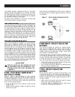
•  Connecting this unit to an electrical system normally supplied 

by an electric utility shall be by means of a transfer switch so as 

to isolate the generator electric system from the electric utility 

distribution system when the generator is operating. Failure to 

isolate the two electric system power sources from each other 

by such means will result in damage to the generator and may 

also result in injury or death to utility power workers due to 

backfeed of electrical energy.

• Generators installed with an automatic transfer switch will 

crank and start automatically when NORMAL (UTILITY) source 

voltage is removed or is below an acceptable preset level. To 

prevent such automatic start-up and possible injury to person-

nel, disable the generator’s automatic start circuit (battery 

cables, etc.) before working on or around the unit. Then, place 

a “Do Not Operate” tag on the generator control panel and on 

the transfer switch.

• In case of accident caused by electric shock, immediately 

shut down the source of electrical power. If  this is not pos-

sible, attempt to free the victim from the live conductor. 

AVOID 

DIRECT CONTACT WITH THE VICTIM.

 Use a nonconducting 

implement, such as a dry rope or board, to free the victim from 

the live conductor. If the victim is unconscious, apply first aid 

and get immediate medical help.

•  Never wear jewelry when working on this equipment. Jewelry 

can conduct electricity resulting in electric shock, or may get 

caught in moving components causing injury.

FIRE HAZARDS

•  Keep a fire extinguisher near the generator at all times. Do NOT 

use any carbon tetra-chloride type extinguisher. Its fumes are 

toxic, and the liquid can deteriorate wiring insulation. Keep the 

extinguisher properly charged and be familiar with its use. If 

there are any questions pertaining to fire extinguishers, consult 

the local fire department.

EXPLOSION HAZARDS

•  Properly ventilate any room or building housing the generator to 

prevent build-up of explosive gas.

• Do not smoke around the generator. Wipe up any fuel or oil 

spills immediately. Ensure that no combustible materials are left 

in the generator compartment, or on or near the generator, as 

FIRE or EXPLOSION may result. Keep the area surrounding the 

generator clean and free from debris.

• All fuel types are potentially FLAMMABLE and/or EXPLOSIVE 

and should be handled with care. Comply with all laws regulat-

ing the storage and handling of fuels. Inspect the unit’s fuel 

system frequently and correct any leaks immediately. Fuel 

supply lines must be properly installed, purged and leak tested 

according to applicable fuel-gas codes before placing this 

equipment into service.

•  Diesel fuels are highly FLAMMABLE.

STANDARDS INDEX

Applicable national, state, or local laws, codes, and regulations 

pertaining to the installation of engine-generator power systems 

must be strictly complied with.  Always use the current accept-

able version or edition of the applicable code or standard.  In the 

absence of pertinent local laws and standards, the following pub-

lished booklets may be used as a guide:

1.  National Fire Protection Association (NFPA) 70: The NATIONAL 

ELECTRIC CODE (NEC) *

2.  NFPA 10: Standard for Portable Fire Extinguishers *
3.  NFPA 30: Flammable And Combustible Liquids Code *
4.  NFPA 37: Standard for Stationary Combustion Engines And Gas 

Turbines *

5.  NFPA 54: National Fuel Gas Code *
6.  NFPA 58: Standard for Storage And Handling Of Liquefied Petroleum 

Gases *

7.  NFPA 68: Standard On Explosion Protection By Deflagration Venting 

*

8.  NFPA 70E: Standard For Electrical Safety In The Workplace *
9.  NFPA 99: Health Care Facilities Code *
10.  NFPA 101: Life Safety Code *
11.  NFPA 110: Standard for Emergency and Standby Power Systems *
12.  NFPA 211:  Standard for Chimneys, Fireplaces, Vents, and Solid Fuel 

Burning Appliances *

13.  NFPA 220: Standard on Types of Building Construction *
14.  NFPA 5000: Building Code *
15.  International Building Code **
16.  Agricultural Wiring Handbook ***
17.  ASAE EP-364.2 Installation and Maintenance of Farm Standby 

Electric Power ****

This list is not all inclusive. Check with the Authority Having Local 

Jurisdiction (AHJ) for any local codes or standards which may be 

applicable. The above listed standards are available from the fol-

lowing internet sources:

*  www.nfpa.org
**  www.iccsafe.org
***   www.rerc.org, Rural Electricity Resource Council P.O. Box 

309Wilmington, OH 45177-0309

****   www.asabe.org, American Society of Agricultural & Biological 

Engineers2950 Niles Road, St. Joseph, MI 49085

Changes to previous standards:  The National Building Code was 

superseded by the International Building Code and/or NFPA 5000 

Building Code. The local AHJ will determine which if either applies.
.

CALIFORNIA PROPOSITION 65 WARNING

Engine exhaust and some of its constituents are known 

to the State of California to cause cancer, birth defects 

and other reproductive harm.

CALIFORNIA PROPOSITION 65 WARNING

This product contains or emits chemicals known to the 

State of California to cause cancer, birth defects and 

other reproductive harm.

Safety Rules

Summary of Contents for SD050

Page 1: ...l should remain with the unit Owner s Manual Stationary Emergency Industrial Generator LISTED C US ONLY QUALIFIED ELECTRICIANS OR CONTRACTORS SHOULD ATTEMPT INSTALLATION Type SD050 Engine D4 5F 1 Mode...

Page 2: ...ions 8 Generator and Load Compatibility 8 Starting Aids 8 Engine Coolant Heaters 8 Battery Chargers 8 Installation 8 Stationary Emergency Generator Installation 9 Units with Enclosures 9 Open Units fo...

Page 3: ...ions before using this equipment The manufacturer also strongly recommends having an authorized Service Dealer provide instruc tion to any designated operators in the safe inspection starting operatin...

Page 4: ...gas if breathed in sufficient concentrations can cause unconsciousness or even death For that reason adequate ventilation must be provided Exhaust gases must be piped safely away from any building or...

Page 5: ...tentially FLAMMABLE and or EXPLOSIVE and should be handled with care Comply with all laws regulat ing the storage and handling of fuels Inspect the unit s fuel system frequently and correct any leaks...

Page 6: ...on L indi cates Level 2 sound attenuation Y indicates a muffler has been mounted N Unit does not have an exhaust muffler L indicates a muffler has been shipped loose with the unit 3 Emission designati...

Page 7: ...TV Monitor etc lighting loads and microwaves THREE PHASE LOAD IMBALANCE LIMITS For three phase units the maximum load imbalance between phases can not exceed 20 of rated load current AMBIENT CONDITIO...

Page 8: ...cification sheet for the unit for the minimum pressure requirement LP FUEL SYSTEM LP is supplied as a liquid in pressure tanks It is usually made up of propane butane or a mixture of the two gases Pro...

Page 9: ...d result Ethylene glycol base antifreeze is poisonous Do not use mouth to siphon coolant from the radiator recovery bottle or any container Wash hands thoroughly after handling Never store used antifr...

Page 10: ...th a an engine coolant heater b an engine oil heater c a battery warmer or d a bat tery charger These aids are powered by a normal utility power source during non operating periods ENGINE COOLANT HEAT...

Page 11: ...tem has been installed do noth ing that might render the installation in non compliance with such codes standards and regulations BASIC STATIONARY EMERGENCY ELECTRIC SYSTEM Figure 2 1 shows a schemati...

Page 12: ...for this unit The instructions in this section assume that the stationary emergency generator has been properly installed serviced tested adjusted and otherwise prepared for use by a competent qualif...

Page 13: ...er switch such as a GTS type switch the engine may be started and stopped automatically or manually NOTE Refer to the applicable manual for the transfer switch and to Transfer Switch Start Signal Conn...

Page 14: ...dule are to be per formed only by an Authorized Service Technician Fluid capacities and recommendations as well as other applicable specifications are listed in Specifications TEST STATIONARY EMERGENC...

Page 15: ...erved Wear full eye protection and protective clothing Where electrolyte contacts the skin wash it off immediately with water Where electrolyte contacts the eyes flush thoroughly and immediately with...

Page 16: ...hould check the levels of engine oil and engine coolant monthly or 10 hours The oil level should be maintained between the FULL and ADD marks on the engine dipstick Recommended fluids are listed are i...

Page 17: ...UST SYSTEM Every three months or 30 hours an authorized operator should inspect the entire exhaust system Abnormal noise levels heard during each operational test may indicate a defective exhaust pipe...

Page 18: ...16 16 Notes...

Page 19: ...placed into service Warranty periods for compression ignition engines greater than 25 horsepower is five years This warranty is applicable to compression ignition generator models equal to and larger...

Page 20: ...rfeit and or gray market parts not made supplied or approved by Generac Warranty service can be arranged by contacting either your selling dealer or a Generac Authorized Warranty Service dealer 1 800...

Page 21: ...d by Federal State or local government Generac or the insurance company associated with the en gine Maintenance checks and readiness testing of such units is limited to 100 hours per year There is no...

Page 22: ...l engine or a part component thereof has failed due to abuse neglect improper maintenance or unapproved modifications or the use of counterfeit and or grey market parts not made supplied or approved b...

Page 23: ...t reduce the ECS Warranty Period Any such part repaired or replaced under the ECS Warranty shall be warranted for the remainder of the ECS Warranty Period 3 Any warranted emissions related part that i...

Page 24: ...repairs outside of normal business hours will be the responsibility of the customer 12 Warranty Parts shipment costs are reimbursed at ground shipment rates Costs related to requests for expedited shi...

Page 25: ...Notes...

Page 26: ......

Page 27: ...Y PCB RELAY 24VDC 0G6962B 1 ASSY PCB RELAY 12VDC 20 0J0392 1 DECAL TB1 LV CUSTOMER CONN 21 0J0398 1 DECAL CONTACT RAT 30VAC 30VDC 22 0J0393 1 DECAL TB2 LV CUSTOMER CONN 23 0J0545 1 DECAL LV CUSTOMER C...

Page 28: ......

Page 29: ......

Page 30: ......

Page 31: ...N SAFETY CODE 9 0J0546 1 DECAL HV CUSTOMER CONN INSIDE 2 11 053640 2 4 SCREW RHM 8 32 X 3 1 4 2 12 038150 2 4 WASHER FLAT 8 ZINC 2 13 022264 2 4 WASHER LOCK 8 M4 2 14 022471 2 4 NUT HEX 8 32 STEEL 20...

Page 32: ...8 8 0J0679 1 DECAL CANADIAN SAFETY CODE 9 0J0546 1 DECAL HV CUSTOMER CONN INSIDE 10 0D3719C REF DECAL CUSTOMER CONN E1 E2 E3 0D3719D REF DECAL CUSTOMER CONN E1 E3 11 0J4466 4 SCREW SHC M4 0 7 X 100 C...

Page 33: ...R LOCK M6 1 4 14 049813 4 NUT HEX M6 1 0 G8 CLEAR ZINC UL CIRCUIT BREAKER LG FRAME 1 1 0H9378HST0R 1 MD1 MODULE COVER 390 LG FRAME 2 0C2454 7 SCREW HWHT M6 1 X 16 N WA Z JS 3 REF 1 CIRCUIT BREAKER 1 4...

Page 34: ......

Page 35: ...15 0441140781 1 WIRE ASM GND 2 0 WIRE 3 8 LUG 16 022131 4 WASHER FLAT 3 8 M10 ZINC 17 049541 2 SCREW HHC M10 1 5 X 35 C8 8 4 3 2 18 0J0455 REF BLOCK TERM 14 POS X 8 X 1600V 4 3 2 19 0J9078 REF DECAL...

Page 36: ......

Page 37: ...2 1 75 X 45 C8 8 1 25 STACK 068406 1 SCREW HHC M12 1 75 X 60 C10 9 2 00 STACK 26 070274 1 KEY SQ 3 8 X 2 3 4 STEEL 27 087271 1 ASSY EXCITER 1 25 STK 087272 1 ASSY EXCITER 2 00 STK 28 068404 1 EXCITER...

Page 38: ......

Page 39: ...0 8 X 16 ZP 8 022097 4 WASHER LOCK M6 1 4 9 022473 4 WASHER FLAT 1 4 M6 ZINC 2 10 056326 2 4 TRIM VINYL BLACK 1 8GP 6 LG 11 0C2454 12 SCREW HWHT M6 1 X 16 N WA Z JS 3 12 022145 4 8 WASHER FLAT 5 16 M8...

Page 40: ......

Page 41: ...1 2 045771 4 6 NUT HEX M8 1 25 G8 CLEAR ZINC 1 3 049897 4 6 SCREW SHC M8 1 25 X 20 G8 1 4 022129 8 12 WASHER LOCK M8 5 16 1 5 022145 8 12 WASHER FLAT 5 16 M8 ZINC 1 6 058306 4 6 SCREW SHC M8 1 25 X 2...

Page 42: ...kW 26kW 048476 4 5A 27kW 130kW 048505 6A 520 mm any 048476 4 5A 0F5752D 75 ohm 1kW 8 9kW 048512 5A 9kW 45kW 048467 7A 1kW 15kW 053623 2 5A 16kW 18kW 049350 4A 19kW 26kW 048476 4 5A 27kW 130kW 048505 6...

Page 43: ......

Page 44: ......

Page 45: ...T HEX M5 0 8 G8 CLEAR ZINC 5 0G3226 1 H PNL I O EXPANSION MOD PROG 6 0E8599A 1 TERMINAL BLK PLUG 2 POS 7 0E8599B 1 TERMINAL BLK PLUG 3 POS 8 0E8599G 1 TERMINAL BLK PLUG 8 POS 9 0G5354 REF MANUAL H PAN...

Page 46: ......

Page 47: ...7 X 283 31 0G4329 1 HARNESS H PNL INTEGRATED SW NOT SHOWN COMPONENTS INCLUDED IN WIRE HARNESS A 0F1263 1 ADPTR RH SIDE WICKMANN 178 6191 B 0F1262 4 HOLDER FUSE WICKMANN 178 6150 C 0F1264 1 ADPTR LH S...

Page 48: ......

Page 49: ...1 4 5 022473 4 WASHER FLAT 1 4 M6 ZINC 6 052857 2 NUT TOP LOCK FL M6 1 0 7 0A4707D 1 ADAPTER 3 8NPT X M16 1 5 8 0A4707E 1 ADAPTER 3 8NPT X M18 1 5 9 0G0015 4 CLAMP HOSE 5 8 DOUBLE WIRE 10 050967 1 HO...

Page 50: ......

Page 51: ...AIR DUCT 1 1 0H85950ST0R 2 AIR DUCT SIDES 1 2 0H85940ST0R 2 AIR DUCT TOP BOTTOM 3 0C2454 16 SCREW THF M6 1 X 16 N WA Z JS NOTES UNLESS OTHERWISE SPECIFIED 1 SHEET METAL PARTS LISTED IN THE BOM TABLE A...

Page 52: ......

Page 53: ...R 1 GUARD 4 5L G17 LEVEL 1 RIGHT 1 4 0J30420ST0R 1 GUARD 4 5L G17 LEVEL 1 UPPER 5 0C2454 9 SCREW HWHT M6 1 X 16 N WA Z JS 1 SHEET METAL PARTS LISTED IN THE BOM TABLE ARE REPRESENTING GENERIC PARTS NO...

Page 54: ......

Page 55: ...INC 16 025507 2 WASHER SHAKEPROOF EXT 7 16 STL 17 051769 1 WASHER LOCK M12 18 052891 4 SCREW HHC M12 1 75 X 80 G8 8 19 0536210307 1 ASSY WIRE 1 14 00 20 049813 1 NUT HEX M6 X 1 0 G8 YEL CHR 21 027482...

Page 56: ......

Page 57: ...2NPT X 8 BLK IRON 16 0J7671 1 FUEL FILL NECK 210MM LONG 4 17 0E3675 2 LABEL 210 GALLON CAPACITY 3 18 021178 1 VENT OEM 2 NPT 19 0C8848 1 NIPPLE PIPE 2NPT X 12 BLK IRON 3 20 072989J 2 3 NPT EMRG PRES V...

Page 58: ......

Page 59: ...0D STREET 1 8 26 0J4574 8 SCREW SHC M10 1 5 X 25 C8 8 27 022145 5 WASHER FLAT 5 16 M8 ZINC 28 022131 20 WASHER FLAT 3 8 M10 ZINC 29 0A4707A 1 ADPATER 1 8NPT X M10 1 0 30 023897 2 WASHER FLAT 10 ZINC 3...

Page 60: ......

Page 61: ...1 HARN RADIATOR GND 80 17 0A4456 1 WASHER LOCK SPECIAL 3 8 18 0E4162 1 CAP RADIATOR 20 PSI 19 026073A 1 PLUG STD PIPE 1 4 STEEL SQ HD 20 029032 1 HOSE 9 32 ID 26 LG 21 048031C 2 REF CLAMP HOSE BAND 5...

Page 62: ......

Page 63: ...LEAR ZINC 10 022129 4 WASHER LOCK M8 5 16 1 11 0J49480ST0R 1 BRACKET AIR CLEANER D4 5L G17 12 022145 2 WASHER FLAT 5 16 M8 ZINC 13 026073 1 PLUG STD PIPE 1 8 STEEL SQ HD 14 057824 2 CLAMP HOSE 16 87 1...

Page 64: ......

Page 65: ...1 GROUP F APPLICABLE TO REVISION A Page 2 of 2 DATE 5 13 11 ITEM PART QTY DESCRIPTION 1 055978 3 BOLT U 3 8 16 X 3 25 2 0A5215C 1 FLEX PIPE 3 3 0H5480 1 ASSY 4 5L OPEN EXHAUST PIPE 4 0J5096 1 PIPE EXH...

Page 66: ......

Page 67: ...16 X 3 50 W SADDLE 4 0J5234 1 EXHAUST ADAPTER 3 OD TO 3 5 ID 5 059940 1 RAIN CAP 3 50 3 69 6 026073 1 PLUG STD PIPE 1 8 STEEL SQ HD 7 0E3603 1 BLANKET MUFFLER WRAP 3 9L L0SE NOT SHOWN 8 0F2773G 1 EXHA...

Page 68: ......

Page 69: ......

Page 70: ......

Page 71: ......

Page 72: ......

Page 73: ......

Page 74: ......

Page 75: ......

Page 76: ......

Page 77: ......

Page 78: ......

Page 79: ......

Page 80: ......

Page 81: ......

Page 82: ......

Page 83: ......

Page 84: ......

Page 85: ......

Page 86: ......

Page 87: ......

Page 88: ......

Page 89: ......

Page 90: ......

Page 91: ......

Page 92: ......

Page 93: ......

Page 94: ......

Page 95: ......

Page 96: ......

Page 97: ...SE 3 8 ID SINGLE BRAID 42 LG 2 0C7649 2 CLAMP HOSE 38 87 3 036865 1 DRAINCOCK 41 8LG BRASS 4 065852 1 SPRING CLIP HOLDER 37 62 5 086292 1 SCREW DRILLTITE 10 16 X 3 4 1 USED IN RADIATOR DRAIN HOSE KIT...

Page 98: ......

Page 99: ...HC 3 8 16 X 1 1 4 G5 6 022237 4 WASHER LOCK 3 8 7 022241 4 NUT HEX 3 8 16 STEEL 8 022131 2 WASHER FLAT 3 8 M10 ZINC 9 045335 4 SCREW HHC 1 4 28 X 3 4 G5 10 022097 4 WASHER LOCK M6 1 4 NEUTRAL BLOCK 70...

Page 100: ......

Page 101: ...1 0C3211E 1 RELAY PNL 12VDC DPDT 8PIN 0C3211F 1 RELAY 24VDC DPDT 8 PIN 1 2 0J0400 1 2 DECAL HV CONNECTION RUN RELAY 3 0C3211H 2 SPRING RELAY RETAINING 1 4 0J5462 2 4 SCREW THTT M4 0 7 X 16 ZP 5 0J083...

Page 102: ......

Page 103: ...5 13 11 ITEM PART QTY DESCRIPTION 1 0H6298 3 WASHER 2 0H6299 1 THREADED UNION 3 0H6297 1 SWIVEL COUPLING 4 0H6295 1 BANJO BOLT M12 1 5 X 25 5 0H6296 1 ELBOW COUPLING 6 048031E 1 CLAMP HOSE BAND 66 7...

Page 104: ......

Page 105: ...HEX M6 1 0 G8 CLEAR ZINC 4 022097 4 WASHER LOCK M6 1 4 5 022473 4 WASHER FLAT 1 4 M6 ZINC NOTES UNLESS OTHERWISE SPECIFEID 1 SHEET METAL PARTS LISTED IN THE BOM TABLE ARE REPRESENTING GENERIC PARTS N...

Page 106: ......

Page 107: ...P H ITEM PART QTY DESCRIPTION REVISION A Page 2 of 2 DATE 11 8 11 1 1 0J7600 1 ADPTR FUEL FILL 2 NPT MALE ALM 2 0G4085 1 DUST CAP 2 TIGHT FILL 1 3 024310 1 PLUG STD PIPE 1 2 STEEL SQ HD 4 0G5835DST03...

Page 108: ...Notes...

Page 109: ...Notes...

Page 110: ...Notes...

Page 111: ......

Page 112: ...GENERAC POWER SYSTEMS INC 211 MURPHY DR P O BOX 310 EAGLE WI 53119 Part No 0J9129 Rev A 04 12...

Reviews: