


9
Only qualified, competent installation contractors or electricians
thoroughly familiar with applicable codes, standards and regula-
tions should install this stationary emergency electric power sys-
tem. The installation must comply strictly with all codes, standards
and regulations pertaining to the installation.
This genset must be installed on a level surface. The base frame
must be level within two (2) inches all around.
UNITS WITH ENCLOSURES
Units with enclosures are designed for outdoor installation only
and must meet all applicable federal, state, and local codes. On
units with enclosures the exhaust system is configured at the fac-
tory. Some applications may require extending the exhaust for safe
operation. In such a case it is best to consult the factory for the
recommended exhaust piping size for the length of run required.
The controlling factor for extending the exhaust piping is the back-
pressure on the engine. Excessive back-pressure on the exhaust
system will lead to unit loss of power, and possible engine and or
exhaust system overheating and engine damage.
OPEN UNITS FOR INDOOR INSTALLATION
Open units are designed for installation in a properly designed
engine room or dedicated generator room. There are many
requirements that need to be met for indoor unit installation with
Fire-Safety being the most important. Other considerations are
providing adequate cooling and combustion air, properly exhaust-
ing the cooling air and the engine exhaust, among other things.
The installation must meet all federal, state and local codes. Open
units are shipped with the muffler or Catalytic convertor (if used)
loose for installation on site. It is important to use the exhaust kits
provided with the unit to insure that the exhaust system operates
as intended. It is also important to consult the installation drawings
for any requirements for length of piping from the engine connec-
tion to the muffler/silencer, the size of the exhaust outlet at the
engine, and any other specific unit requirements.
After the system has been installed, do noth-
ing that might render the installation in non-
compliance with such codes, standards and
regulations.
BASIC STATIONARY EMERGENCY
ELECTRIC SYSTEM
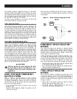
Figure 2.1 shows a schematic diagram of a basic stationary
emergency electric system. Both the UTILITY power supply and
the STANDBY (GENERATOR) output are connected to an approved
transfer switch. The transfer switch is required by electrical code
and serves the following functions:
• Permits the LOAD circuits to be connected to only one power
supply at a time.
• Prevents electrical backfeed between the generator and the
UTILITY power circuits.
Notice that both the STANDBY and the UTILITY power supplies to
the transfer switch are protected against overload by a main line
circuit breaker.
Figure 2.1 – Basic Stationary Emergency Electric
System
EMERGENCY CIRCUIT ISOLATION
METHOD
This prevents overloading the generator by keeping electrical
loads below the wattage/amperage capacity of the generator. If
the generator is powering only critical loads, within the wattage/
amperage capacity, during utility power outages, consider using
the emergency circuit isolation method.
Critical electrical loads are grouped together and wired into a sepa-
rate “Emergency Distribution Panel.” Load circuits powered by that
panel are within the wattage/amperage capacity of the generator
set. When this method is used, it is difficult to overload the gen-
erator. The transfer switch must meet the following requirements:
• It must have an ampere rating equal to the total amperage rating
of the emergency distribution panel circuit.
• Have it installed between the building’s main distribution panel
and the emergency distribution panel.
TOTAL CIRCUIT ISOLATION
METHOD
When a generator capable of powering all electrical loads in the
circuit is to be installed, use the “Total Circuit Isolation Method.” It
is possible for the generator to be overloaded when this isolation
method is employed. The following apply to the transfer switch in
this type of system.
• Ampere rating of the transfer switch must equal the ampere
rating of the normal incoming utility service.
• The transfer switch is installed between the utility service
entrance and the building distribution panel.
Installation
Summary of Contents for SD050
Page 18: ...16 16 Notes...
Page 25: ...Notes...
Page 26: ......
Page 28: ......
Page 29: ......
Page 30: ......
Page 34: ......
Page 36: ......
Page 38: ......
Page 40: ......
Page 43: ......
Page 44: ......
Page 46: ......
Page 48: ......
Page 50: ......
Page 52: ......
Page 54: ......
Page 56: ......
Page 58: ......
Page 60: ......
Page 62: ......
Page 64: ......
Page 66: ......
Page 68: ......
Page 69: ......
Page 70: ......
Page 71: ......
Page 72: ......
Page 73: ......
Page 74: ......
Page 75: ......
Page 76: ......
Page 77: ......
Page 78: ......
Page 79: ......
Page 80: ......
Page 81: ......
Page 82: ......
Page 83: ......
Page 84: ......
Page 85: ......
Page 86: ......
Page 87: ......
Page 88: ......
Page 89: ......
Page 90: ......
Page 91: ......
Page 92: ......
Page 93: ......
Page 94: ......
Page 95: ......
Page 96: ......
Page 98: ......
Page 100: ......
Page 102: ......
Page 104: ......
Page 106: ......
Page 108: ...Notes...
Page 109: ...Notes...
Page 110: ...Notes...
Page 111: ......
Page 112: ...GENERAC POWER SYSTEMS INC 211 MURPHY DR P O BOX 310 EAGLE WI 53119 Part No 0J9129 Rev A 04 12...


