


10
GROUNDING THE GENERATOR
The generator set must be grounded in accordance with the
National Electrical Code and any state or local requirements.
DO NOT connect the ground wire to any pipe
that carries a flammable or explosive sub-
stance – FIRE or an EXPLOSION may result.
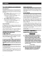
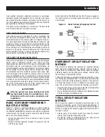
Figure 2.2 – Grounding Electrode Terminal (typical)
Base Frame
Grounding Electrode Terminal
GENERATOR AC NEUTRAL
CONNECTIONS
Grounding is recommended only at one point in the system.
Consult local building codes for proper neutral grounding require-
ments.
INITIAL START-UP
The initial startup of this stationary emergency electrical system
must be performed and documented by an authorized Service
Dealer. Failure to do so will void the manufacturer's warranty.
Prior to initially starting the generator, it
must be properly prepared for use. Any
attempt to crank or start the engine before
it has been properly serviced with the rec-
ommended types and quantities of engine
fluids (oil, coolant, fuel, etc.) may result in an
engine failure.
For diesel units use a suitable container to
catch the fuel that will spill during system
bleeding process. Clean up all spilled fuel
after bleeding.
GENERATOR CONTROL AND
OPERATION
The operation of this stationary emergency electrical system should
only be performed by an Authorized Operator. An "Authorized
Operator" is someone who has been properly trained by an
Authorized Service Dealer. For assistance in training authorized
operators please contact your local Authorized Service Dealer.
Refer to the appropriate control panel operator’s manual for this
unit. The instructions in this section assume that the stationary
emergency generator has been properly installed, serviced, tested,
adjusted and otherwise prepared for use by a competent, qualified
installation contractor and Authorized Service Dealer. Be sure to
read the “Safety Rules” as well as all other safety information in
this manual, before attempting to operate this (and related) equip-
ment.
OPERATING UNIT WITH MANUAL
TRANSFER SWITCH
If the generator was installed in conjunction with a transfer switch
capable of manual operation only, the following procedure applies.
A manually operated transfer switch is one that will not provide
automatic start-up and does not include an intelligence circuit.
ENGINE START-UP AND TRANSFER
For additional information, refer to the applicable control panel
manual for this unit, as well as any literature pertaining to the
transfer switch.
The Maintenance Disconnect Switch and
the AUTO/OFF/MANUAL switches (if so
equipped) must be set properly, or the
generator will crank and start as soon as
the UTILITY power to the transfer switch is
turned off. Refer to applicable control panel
and transfer switch manuals for more infor-
mation.
Do not proceed until certain that utility
source voltage is available to the transfer
switch and the transfer switch main contacts
are set to UTILITY.
Do not attempt manual operation until all
power supplies to the transfer switch have
been positively turned OFF, or extremely dan-
gerous — possibly lethal — electrical shock
will result.
Transfer switch enclosure doors should be
kept closed and locked. Only authorized
personnel should be allowed access to the
transfer switch interior. Extremely high and
dangerous voltages are present in the trans-
fer switch.
Operation
Summary of Contents for SD050
Page 18: ...16 16 Notes...
Page 25: ...Notes...
Page 26: ......
Page 28: ......
Page 29: ......
Page 30: ......
Page 34: ......
Page 36: ......
Page 38: ......
Page 40: ......
Page 43: ......
Page 44: ......
Page 46: ......
Page 48: ......
Page 50: ......
Page 52: ......
Page 54: ......
Page 56: ......
Page 58: ......
Page 60: ......
Page 62: ......
Page 64: ......
Page 66: ......
Page 68: ......
Page 69: ......
Page 70: ......
Page 71: ......
Page 72: ......
Page 73: ......
Page 74: ......
Page 75: ......
Page 76: ......
Page 77: ......
Page 78: ......
Page 79: ......
Page 80: ......
Page 81: ......
Page 82: ......
Page 83: ......
Page 84: ......
Page 85: ......
Page 86: ......
Page 87: ......
Page 88: ......
Page 89: ......
Page 90: ......
Page 91: ......
Page 92: ......
Page 93: ......
Page 94: ......
Page 95: ......
Page 96: ......
Page 98: ......
Page 100: ......
Page 102: ......
Page 104: ......
Page 106: ......
Page 108: ...Notes...
Page 109: ...Notes...
Page 110: ...Notes...
Page 111: ......
Page 112: ...GENERAC POWER SYSTEMS INC 211 MURPHY DR P O BOX 310 EAGLE WI 53119 Part No 0J9129 Rev A 04 12...


