


Maintenance
14
Maintenance
Gaseous Engine
Battery Size
Minimum CCA
2.4L
GRP 26
525
4.2L
GRP 24F
or GRP 27F
525
700
5.4L
GRP 24F, GRP 27F
or 2 X GRP 31
525
700
6.8L
12.9L
2 X GRP 31
or 2 GRP 8D
925
13.3L
Fill the battery with the proper electrolyte fluid if necessary and
have the battery fully charged before installing it.
Before installing and connecting the battery, complete the following
steps:
1. Set the generator's AUTO/OFF/MANUAL switch to OFF.
2. Turn off utility power supply to the battery charger circuit.
3. Remove the 10A and 15A fuses from the generator control
panel.
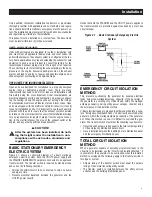
Battery cables were factory connected at the generator connection
points (Figure 1.4). Connect cables to battery posts as follows:
4. Connect the red battery cable (from starter contactor) to the
battery post indicated by a positive, POS or (+).
5. Connect the black battery cable (from frame ground) to the
battery post indicated by a negative, NEG or (—).
6. Reinstall the 10A and 15A fuses into their correct positions
inside the control panel.
7. Turn on the utility power supply to the battery charger circuit.
8. If the unit was previously operational turn the AUTO/OFF/
MANUAL switch back to the AUTO position.
Figure 1.4 – Battery Cable Connections
NOTE:
Damage will result if battery connections are made in reverse.
NOTE:
The generator is equipped with a battery trickle charger that is
active when the unit is set up for automatic operation. With the
battery installed and utility power source voltage available, the
battery receives a trickle charge while the engine is not run-
ning, to prevent self-discharge. The trickle charger is designed
to help extend the life of the battery by maintaining the battery
when the unit is not running. The trickle charge feature cannot
be used to recharge a discharged battery.
CHECK FLUIDS
An authorized operator should check the levels of engine oil, and
engine coolant monthly (or 10 hours). The oil level should be
maintained between the “FULL” and “ADD” marks on the engine
dipstick. Recommended fluids are listed are in the "Specifications"
section.
Check the engine oil as follows:
1. Locate the engine oil dipstick.
2. The most accurate oil level readings are measured when the
engine is cold. If the engine was running,
wait at least 10
minutes
before proceeding to the next step.
3. Remove the dipstick and wipe dry with a clean, lint free cloth.
4. The clean dip stick should be
slowly
inserted into the dip stick
tube. Visually confirm that the dip stick is fully seated in the
dip stick tube. A visual inspection is required because some
dip sticks will require more effort than others to fully seat.
5. After
10 seconds
have passed, remove the dip stick.
6. Look at the oil level on
both sides
of the dip stick. The
lower
of the two readings will be the correct oil level measurement.
7. Adjust the oil level accordingly. After adding or changing the
oil, the engine should run for one minute before checking the
oil level according to the above procedure starting at step 1.
You must wait the full 10 minutes to ensure that the oil has
fully drained into the oil pan.
Typical root causes of inaccurate oil level readings:
• Reading the high level of the dip stick.
• Reading the dip stick before the oil fully drains into the oil pan
(step #2).
• Inserting and removing the dip stick too quickly (step #5).
• Dip stick isn’t fully seated in the dip stick tube.
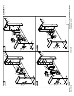
CHECK GEARBOX OIL (IF EQUIPPED)
Once annually (or at every 200 hour intervals), an authorized ser-
vice technician should completely drain and refill the gearbox (if so
equipped) using the following procedure (Figure 4.1):
1. Remove panel fuse and negative battery cable.
2. Remove the oil filler/vent cap.
3. Remove the drain plug and drain the oil into an appropriate
container. Dispose of or recycle the oil properly.
4. Reinstall the oil drain plug.
5. To add oil to the gearbox, remove the oil level check plug.
Summary of Contents for SD050
Page 18: ...16 16 Notes...
Page 25: ...Notes...
Page 26: ......
Page 28: ......
Page 29: ......
Page 30: ......
Page 34: ......
Page 36: ......
Page 38: ......
Page 40: ......
Page 43: ......
Page 44: ......
Page 46: ......
Page 48: ......
Page 50: ......
Page 52: ......
Page 54: ......
Page 56: ......
Page 58: ......
Page 60: ......
Page 62: ......
Page 64: ......
Page 66: ......
Page 68: ......
Page 69: ......
Page 70: ......
Page 71: ......
Page 72: ......
Page 73: ......
Page 74: ......
Page 75: ......
Page 76: ......
Page 77: ......
Page 78: ......
Page 79: ......
Page 80: ......
Page 81: ......
Page 82: ......
Page 83: ......
Page 84: ......
Page 85: ......
Page 86: ......
Page 87: ......
Page 88: ......
Page 89: ......
Page 90: ......
Page 91: ......
Page 92: ......
Page 93: ......
Page 94: ......
Page 95: ......
Page 96: ......
Page 98: ......
Page 100: ......
Page 102: ......
Page 104: ......
Page 106: ......
Page 108: ...Notes...
Page 109: ...Notes...
Page 110: ...Notes...
Page 111: ......
Page 112: ...GENERAC POWER SYSTEMS INC 211 MURPHY DR P O BOX 310 EAGLE WI 53119 Part No 0J9129 Rev A 04 12...


