Operation
Owner’s Manual for Generac PWRmanager 12 Relay Load Controller
5
Section 3: Operation
Before using the PWRview app to manage circuits, the
PWRmanager must be wired, configured, and registered
by the installer.
Download the Generac PWRview app from Google Play
or the Apple App Store. Log in using the email the PWR
-
cell system is registered to. Follow the sections below to
configure automatic control, and to control loads directly
from the app.
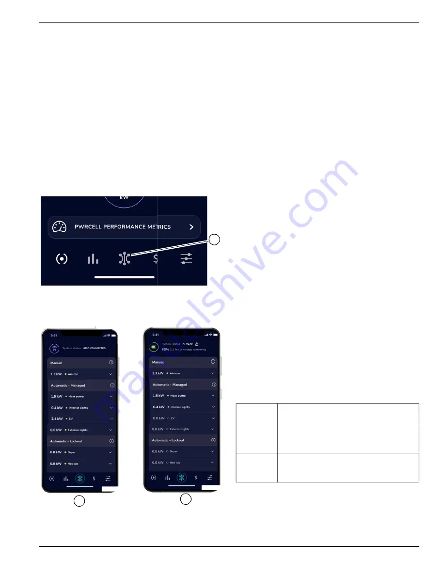
Circuits List Screen in PWRview
Once the PWRmanager is registered, a new screen will
be added in the app. To view that screen, tap on the Cir
-
cuits List icon in the center of the navigation bar (A) See
Figure 3-1. Circuits List Icon
There are several elements to the circuits list screen
described below.
Figure 3-2. Circuits List Screen
Power Source Header
See
. At the top of the screen in (A), the
header shows the grid icon which indicates that the sys
-
tem is grid connected.
When in an outage (B), the header shows the battery
icon, state of charge, and an estimate for how long the
battery will last.
Circuit Groups
Loads wired to connect through the PWRmanager during
installation will appear in groups based on how they are
currently controlled.
Manual Group
See
. Circuits configured as manual on or off
appear at the top of the list below the power source
header. If no circuits are manually controlled, this section
will not appear.
Automatic - Managed Group
See
. Prioritized circuits appear in the upper
group of the Circuits List screen: circuits at the top of this
section will be disabled last when available power capac
-
ity reduces.
Automatic - Lockout Group
Lockout Loads appear in the bottom portion of the Cir
-
cuits List screen, as shown in
. These are
shed immediately upon entering an outage. This helps
conserve battery energy to last through longer outages
and prevent overloading the PWRcell system.
System Status and Settings
See
. When scrolling down to the bottom of
the Circuits List screen, a button to bring up the system
status of the unit will appear. Tap on it to see the following
status information for the PWRmanager:
A
012946
012947
A
B
Internet
This indicates if the PWRmanager unit is
connected to the internet.
System
If an error has occurred in the PWRman
-
ager or a circuit error exists, it will be indi
-
cated here.
Switch
Position
Shows the position of the Mode Selector
Knob. If it isn’t in “Normal”, the system
will not function correctly.
Summary of Contents for PWRmanager
Page 23: ......


